Woodward UG-25+ Installation And Operation Manual
Hide thumbs
Also See for UG-25+:
- Application note (10 pages) ,
- Security manual (22 pages) ,
- Installation procedure supplement (5 pages)

Related Manuals for Woodward UG-25+


Summary of Contents for Woodward UG-25+
- Page 1 Product Manual 26580 (Revision D, 9/2018) Original Instructions UG-25 Actuator Installation and Operation Manual...
- Page 2 Revisions— A bold, black line alongside the text identifies changes in this publication since the last revision. Woodward reserves the right to update any portion of this publication at any time. Information provided by Woodward is believed to be correct and reliable. However, no responsibility is assumed by Woodward unless otherwise expressly undertaken.
-
Page 3: Table Of Contents
Product Support Options ..........................46 Product Service Options ..........................46 Returning Equipment for Repair ......................... 47 Replacement Parts ............................48 Engineering Services ..........................48 Contacting Woodward’s Support Organization ................... 48 Technical Assistance ..........................49 A. A ................. 50 PPENDIX CRONYMS BBREVIATIONS B. - Page 4 Actuator Functional Overview..........39 Table 3-1. Customer I/O Terminal Position Assignment ................32 Table 5-1. Engine/Generator Troubleshooting.................... 44 Table B-1. Power Input (1 and 2) ........................ 53 Table B-2. Status (Unit Health) Output ....................... 53 Table B-3. Position Command ........................53 Woodward...
-
Page 5: Warnings And Notices
Start-up On- and off-highway Mobile Applications: Unless Woodward's control functions as the supervisory control, customer should install a system totally independent of the prime mover control system that... -
Page 6: Electrostatic Discharge Awareness
Do not touch the components or conductors on a printed circuit board with your hands or with conductive devices. To prevent damage to electronic components caused by improper handling, read and observe the precautions in Woodward manual 82715 , Guide for Handling and Protection of Electronic Controls, Printed Circuit Boards, and Modules. -
Page 7: Regulatory Compliance
Special Conditions for Safe Use: Field wiring must be suitable for at least 55 °C. Compliance with the Machinery Directive 2006/42/EC noise measurement and mitigation requirements is the responsibility of the manufacturer of the machinery into which this product is incorporated. Woodward... - Page 8 Manual 26580 UG-25+ Actuator Safety Symbols Direct Current Alternating Current Both Alternating and Direct Current Caution, risk of electrical shock Caution, refer to accompanying documents Protective conductor terminal Frame or chassis terminal Woodward...
-
Page 9: Chapter 1. General Information
Specifications and Troubleshooting information are provided in the Appendixes. General Description The Woodward UG-25 actuator is a microprocessor controlled mechanical hydraulic actuator used in conjunction with an external governor for controlling diesel, gas, or dual fuel engines, or steam turbines. -
Page 10: Ug Governor Similarities
Governor Linkage for Butterfly Control Valve 03386 UG-25 Actuator Product Specification 36684 Booster Servomotor Contact your nearest Woodward Distributor or Authorized Independent Service Facility about repairs. Serviceability The UG-25 actuator has no field-replaceable parts. The UG-25 actuator is not equipped with an overspeed trip function. -
Page 11: Figure 1-1A
Manual 26580 UG-25+ Actuator Figure 1-1a. UG-25 Actuator Outline Drawing Woodward... -
Page 12: Figure 1-1B
Manual 26580 UG-25+ Actuator Figure 1-1b. UG-25 Actuator Outline Drawing Woodward... -
Page 13: Figure 1-2. Ug-25 Drive Shaft Configurations
Manual 26580 UG-25+ Actuator Figure 1-2. UG-25 Drive Shaft Configurations Woodward... -
Page 14: Chapter 2. Mechanical Installation
Chapters 2 and 3, Installation Procedures and Electrical Installation. Make sure that all installation steps have been correctly accomplished and all linkages are secured and properly attached. Carefully review the direction of rotation for the actuator oil pump. Woodward... -
Page 15: Unpacking
Unpacking Be careful when unpacking the unit. Check the unit for signs of damage, such as bent or dented panels, scratches, and loose or broken parts. Notify the shipper and Woodward if damage is found. Receiving After factory testing and calibration, the UG-25 actuator is drained of oil. -
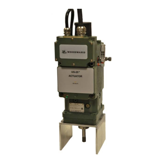
Page 16: Figure 2-1. Ug-25 + Actuator Overview
Manual 26580 UG-25+ Actuator Figure 2-1. UG-25 Actuator Overview Woodward... -
Page 17: Drive Shaft Rotation
For long-term storage (more than a year), storage in an environment with large temperature changes, humid or corrosive atmosphere, etc., or if the actuator is installed on the engine for storage, fill the actuator with oil and follow preservation packaging instructions in Woodward manual 25075, Commercial Preservation Packaging for Storage of Mechanical-Hydraulic Controls. - Page 18 The mounting hole must be concentric with the drive in order to avoid side-loading the UG-25 actuator drive shaft. (This O-ring part number 1355-308 can be ordered separately from Woodward.) Lifting Method When mounting the UG-25 on the engine, a lifting sling can be used as shown in the photo below.
-
Page 19: Drive Connection
Misadjusted linkage could prevent the actuator from shutting down the engine. Woodward... -
Page 20: Figure 2-3. Terminal Shaft Travel
Installed linkages must operate smoothly, be free of binding, and free of lost motion due to worn parts. If there is a collapsible member in the linkage, be sure it does not yield each time the actuator moves the linkage rapidly. Figure 2-3. Terminal Shaft Travel Woodward... -
Page 21: Oil Supply
Oil Supply See Woodward manual 25071, Oils for Hydraulic Controls, for more details on oil supply. Use the information given in Figures 2-5 and 2-6 as a guide in the selection of a suitable oil. Oil grade selection is based on the operating temperature range of the actuator. Also use this information to aid in recognizing and correcting common problems associated with oil used in the actuator. -
Page 22: Figure 2-6. Oil Chart
2.1 liters (2.2 quarts) of oil, to a level visible in the oil sight glass. After the engine is started and the actuator is at operating temperature, add oil if necessary. Oil must be visible in the glass under all operating conditions. Woodward... - Page 23 Regularly scheduled oil changes will extend the life of the actuator and improve actuator operation. Properly selected oil should permit annual oil changes, but more frequent changes are recommended. Too long an interval between oil changes can result in sticking of components and plugged oil passages. Woodward...
-
Page 24: Heat Exchanger
Woodward recommends overhauling the UG-25+ actuator to inspect for wear and to replace seals, bearings, etc. The overhaul interval of the UG-25+ will be dependent on the application. Woodward recommends using the same interval as the engine. Units may need to be re-manufactured/overhauled before that time if there is oil leakage, parts become loose, or if the unit experiences severe operating conditions of heat or vibration. -
Page 25: Chapter 3. Electrical Installation
(unpainted) metal. Figure 3-1. Location of Ground Strap Do not connect any cable grounds to “instrument ground”, “control ground”, or any non-earth ground system. Make all required electrical connections based on the wiring diagrams (Figures 3-2 and 3-3). Woodward... -
Page 26: Shielded Wiring
Remove the wiring access cover plate located on the front of the User Interface panel by removing the six M4 x 0.7, 10 mm long locking screws (Woodward part number 1031-1806) to access all customer field connection terminal blocks. Securely replace the wiring cover plate after completing the wiring... -
Page 27: Figure 3-2. Access Cover Instruction Label
Strip approximately 10 mm (0.4 inch) of insulation from each individual signal wire and crimp on a wire ferrule, Woodward part number 1606-667 (Phoenix part number 3200043) for 16 AWG wire, to the end of each signal wire. Use the proper crimp tool, “CRIMPFOX 6H” Woodward part number 8996-2197 (Phoenix part number 12 12 046) to crimp the ferrules onto the signal wires with a hexagonal crimp. -
Page 28: Figure 3-4. Correct And Incorrect Dome Nut Installation
When routing cables, allow a sufficient service loop when routing the cable around corners. Two customer cable clamp mounting holes are located on the top, front corners of the User Interface panel and accept M5 x 0.8, 10 mm long screws, Woodward part number 1029-972. Woodward... -
Page 29: Figure 2-1
ALLOWS THE CUSTOMER TO ‘HARD GROUND’ THE SHIELD ON THE OPPOSITE END OF THEIR CABLE, IF DESIRED. HI-POT JUMPER MUST BE INSTALLED FOR NORMAL OPERATION AND MUST BE REMOVED ONLY DURING A HI-POT TEST, THEN RE-INSTALLED FOR OPERATION. Figure 3-5. UG-25 Actuator Application Wiring Woodward... -
Page 30: Figure 3-6A. Connector Wiring
Do not connect any cable grounds to “instrument ground”, “control ground”, or any non-earth ground system. Make all required electrical connections based on the wiring diagrams (Figures 3-2 and 3-3). The Hi-Pot jumper must be installed for normal operation, and must be removed only during a Hi-Pot test. Woodward... -
Page 31: Figure 3-6B. Connector Wiring
Manual 26580 UG-25+ Actuator Figure 3-6b. Connector Wiring Woodward... -
Page 32: Figure 3-6C. Connector Wiring
Manual 26580 UG-25+ Actuator Figure 3-6c. Connector Wiring Woodward... -
Page 33: Figure 3-6D
Manual 26580 UG-25+ Actuator Figure 3-6d. UG-25 Actuator Terminals Woodward... - Page 34 20 (TB4-4) Power Input – Input (dc) Supply Input. Return for (18 to 32) V 21 (TB4-5) Power Input – Input (dc) Supply Input. Supply Power, (18 to 32) 22 (TB4-6) Power Input + Input V (dc), 1.5 A max. Woodward...
-
Page 35: Figure 3-4. Internal Block Diagram
UG-25 actuator will not power-up. Woodward recommends using a 6 A fuse on the power supply line feeding Terminals 19 and 22 of the UG-25+ actuator. The input power must be fused. Failure to fuse the UG-25... -
Page 36: Figure 3-5. Correct And Incorrect Wiring To Power Supply
UG-25+ Actuator Figure 3-5. Correct and Incorrect Wiring to Power Supply Woodward recommends using a standard 6 A fuse on the (18 to 32) V (dc) input as show in Figure 3-2. Do NOT use a slow-blow-type fuse in this application. -
Page 37: High Potential Testing
Before performing any insulation resistance testing, remove the small HI-POT jumper, Woodward part number 2008-1443, located between Terminals 17 and 18, which is found under the wiring access cover plate on the front of the User Interface panel. - Page 38 Install the jumper between Terminals 17 and 18 for normal operation. The UG-25 actuator may be damaged by power surges if this jumper is not properly installed. Woodward...
-
Page 39: Chapter 4. Description Of Operation
Analog inputs are differential type with extra filtering for common-mode noise rejection. The control provides one discrete output, which provides a Unit Healthy indication. The UG-25 actuator should not be used as the primary means of shutting down the engine. Woodward... -
Page 40: Principal Of Operation
The terminal shaft lever converts the linear motion of the differential-type power piston into a rotary motion of the terminal shaft, which in turn moves the fuel linkage. The terminal-shaft position is fed back to the pilot valve to provide the proportional control. Woodward... -
Page 41: Figure 4-2. Ug-25 Actuator Functional Overview
As the power piston rises, the power piston rod moves with it and rotates the terminal shaft, converting the output motion back to rotary. One end of the floating lever is directly connected to the power piston rod and this end rises correspondingly. Woodward... -
Page 42: Fault Detection And Annunciation
If the on-board temperature sensor reads a temperature above 125 °C, this error will be set. The Current Limiting based on temperature will effectively make the output "limp" by reducing the drive current to zero (see Current Limiting Based on Temperature section for details). Woodward... - Page 43 If detected, the control output will go limp. A power cycle is required to clear this fault. This shutdown causes the Unit Healthy LED to turn off and the External Status output (Terminal 11) to open-circuit, turning off any External Status device that is connected. Woodward...
-
Page 44: Chapter 5. Troubleshooting
General System Troubleshooting Guide The following is a general troubleshooting guide for areas to check which may present potential difficulties. Make these checks before contacting Woodward for technical assistance. • Is the wiring correct? Refer to wiring diagram Figure 3-2. - Page 45 Flush the actuator once again. Refill the actuator with oil (see Chapter 2, Oil Supply). Restart the engine. 5. Check that the drive to the actuator is correctly aligned and free of roughness, side loading, and excessive backlash. Woodward...
-
Page 46: Table 5-1. Engine/Generator Troubleshooting
If the problem is still there, replace the actuator. If the hunting and/or surging continues, the problem is in the prime mover. Oil varnish, which causes sticking Return the actuator to a Woodward authorized service of parts. facility for overhaul. Dirty oil (sludge) in actuator. - Page 47 Verify Unit Healthy Status LED functionality. Both Discrete out and LED are driven from the same controller terminal and should activate together (L-Series Terminal B on TB5-2). Verify on/off command signal to discrete out using Service Tool (overview tab). Woodward...
-
Page 48: Chapter 6. Product Support And Service Options
• An Authorized Independent Service Facility (AISF) provides authorized service that includes repairs, repair parts, and warranty service on Woodward's behalf. Service (not new unit sales) is an AISF's primary mission. • A Recognized Turbine Retrofitter (RTR) is an independent company that does both steam and gas turbine control retrofits and upgrades globally, and can provide the full line of Woodward systems and components for the retrofits and overhauls, long term service contracts, emergency repairs, etc. -
Page 49: Returning Equipment For Repair
All repair work carries the standard Woodward service warranty (Woodward Product and Service Warranty 5-01-1205) on replaced parts and labor. -
Page 50: Replacement Parts
• The unit serial number, which is also on the nameplate Engineering Services Woodward offers various Engineering Services for our products. For these services, you can contact us by telephone, by email, or through the Woodward website. • Technical Support •... -
Page 51: Technical Assistance
UG-25+ Actuator Technical Assistance If you need to contact technical assistance, you will need to provide the following information. Please write it down here before contacting the Engine OEM, the Packager, a Woodward Business Partner, or the Woodward factory: General... -
Page 52: Appendix A. Acronyms / Abbreviations
Clockwise CMRR Common-Mode Rejection Ratio Cyclic Redundancy Count Electro-Magnetic Compatibility Inputs/Outputs L-Series Woodward electronic engine governor that contains both a rotary governor and a controller circuit board O.D. Outside Diameter Original Equipment Manufacturer Proportional/Integral/Derivative Parts Per Million Travel Position Sensor... -
Page 53: Appendix B. Ug-25+ Governor Specifications
335 W (0.45 hp) max Internal Hydraulic Pressure: 1034 kPa (150 psi) Oil: Self-contained sump (2.2 qt/2.1 L capacity). See Woodward Manual 25071, Oils for Hydraulic Controls, for oil recommendations. Drive Rotation: Pump can be configured to operate in CW or CCW direction... - Page 54 IP45 for Entire Unit, IP56 for User Interface per EN60529 and only if proper cable glands are used as described in this manual. Functions I/O: 4–20 mA analog speed setting; Position Command control signal Unit Healthy discrete out Front Panel Indications: Unit Healthy status indication Woodward...
-
Page 55: Table B-1. Power Input (1 And 2)
Input Impedance Anti-Aliasing Filter 1 anti-aliasing pole at 0.47 ms (338 Hz) Resolution 10 bits Accuracy ±0.8 % of full scale at 25 °C Drift 80 ppm/°C I/O Latency 6.5 ms CMRR 60 dB Common-Mode Range 45 V (dc) Woodward... -
Page 56: Revision History
Changes in Revision B— • Updated Regulatory Compliance information • Added fire protection warning (page 7) • Removed Hazardous Location & UL information (pages 16/17/18/23/37) • Added Declarations Changes in Revision A— • Figure 1-1—Updated call-outs • Figure 1-2—Updated dimension lines Woodward... -
Page 57: Eclarations
Manual 26580 UG-25+ Actuator Declarations Woodward... - Page 58 Manual 26580 UG-25+ Actuator Woodward...
- Page 59 Manual 26580 UG-25+ Actuator THIS PAGE INTENTIONALLY LEFT BLANK Woodward...
- Page 60 Email and Website—www.woodward.com Woodward has company-owned plants, subsidiaries, and branches, as well as authorized distributors and other authorized service and sales facilities throughout the world. Complete address / phone / fax / email information for all locations is available on our website.
Need help?
Do you have a question about the UG-25+ and is the answer not in the manual?
Questions and answers
Hello how are you sir I **** working on Hyundai himsen diesel engine generator and actuator fitted here Woodward UG 25 SO I want to know that which oil used in this actuator.because no manual available in this site.thanks
The Woodward UG-25+ actuator uses oil that functions as both a lubricating and hydraulic oil. The oil must have a viscosity index suitable for the actuator's operating temperature range and include additives to ensure stability and predictability. Oil selection should follow the guidelines in Figures 2-5 and 2-6 of the manual, ensuring the viscosity at operating temperature remains between 50 SUS and 3000 SUS. The specific oil type for a Hyundai Himsen diesel engine generator is not explicitly mentioned, but it should meet these requirements.
This answer is automatically generated