Table of Contents
Advertisement
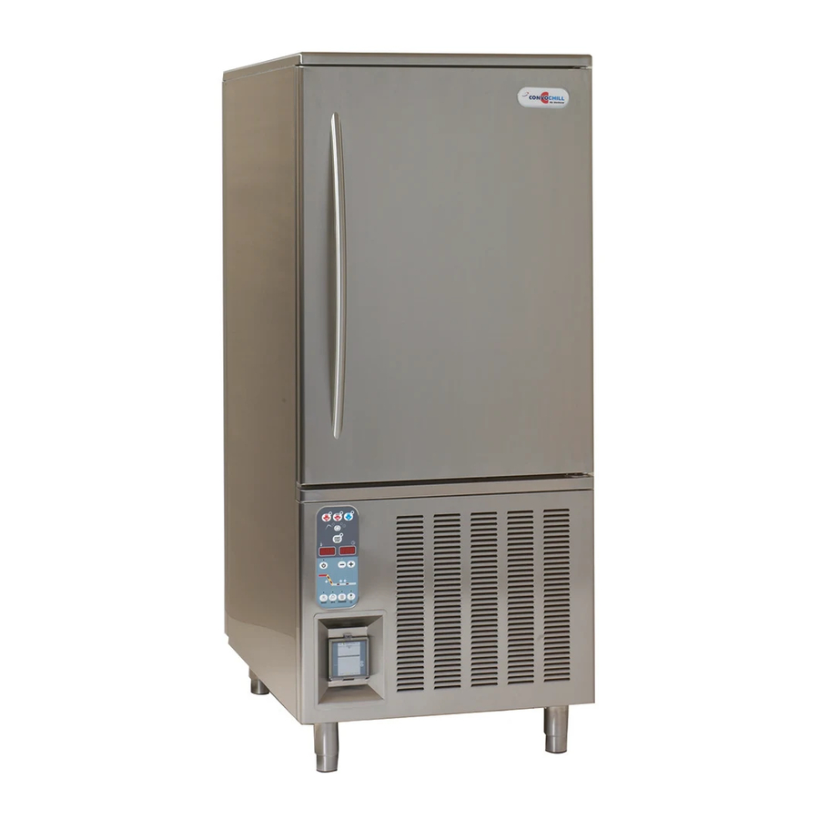
T5, T14D, T20C, T24C, T40
Blast Chiller/Shock Freezers
Service, Installation and Care Manual
Please read this manual completely before attempting to install or operate this equipment! Notify carrier of
damage! Inspect all components immediately. See page 2.
Blast Chillers/Shock Freezers
Effective Date August 2006
Advertisement
Table of Contents

Related Manuals for Delfield T14D


Summary of Contents for Delfield T14D
- Page 1 T5, T14D, T20C, T24C, T40 Blast Chiller/Shock Freezers Service, Installation and Care Manual Please read this manual completely before attempting to install or operate this equipment! Notify carrier of damage! Inspect all components immediately. See page 2. Blast Chillers/Shock Freezers...
-
Page 2: Table Of Contents
CONTENTS GENERAL DOCUMENTATION General information Installation Transport and handling Unpacking - disposal of packaging materials General safety regulations INSTALLATION Data plate information Positioning Ambient temperature and air circulation Electrical connections Refrigeration component connections - remote assemblies Condensate drainage connection Information for the installation technician Safety and control systems Appliance disposal ADVICE TO ENSURE EFFICIENT APPLIANCE OPERATION... - Page 3 APPLIANCE FUNCTIONS Date and time settings Ice cream surface hardening Muting the beeper and alarm reset Program storage Displaying the three latest HACCP alarms Printing out stored data Forced ventilation function User programming Manual defrosting 6.10 Automatic defrost cycles ALARM MANAGEMENT Storage of data/errors Alarms list MAINTENANCE AND CLEANING...
-
Page 4: General Documentation
In the event that the machine is fitted with a remote condenser unit, the installation technician is responsible for checking all connections in compliance with the instructions given by Delfield for plant and machine installation. 1.3 Transport and handling • To load or unload the machine and/or... -
Page 5: Installation
100°F / 38°C. Remote condensing units may be installed indoors next to the unit or within 25 ft. Consult Delfield if placementwill be greater than 25 ft. away. Remote condensing units may also be installed outdoors but require a U.L. listed enclosure which is supplied as an option from Delfield. -
Page 6: Condensate Drainage Connection
2.6 Condensate drainage connection For models T20C-T24C-T40 fit a condensate water drainage hose with a minimum diameter of 1” . Provide a waste pipe with a trap with a diameter of at least 1 1/2” at floor level. 2.7 Information for the installation technician Before starting up the machine, check that it has been correctly installed. -
Page 7: Advice To Ensure Efficient Appliance Operation
3. ADVICE TO ENSURE EFFICIENT APPLIANCE OPERATION 3.1 Shut-down procedures In the event of emergency, shut down the appliance by switching off power at the main panel, by means of a breaker or power disconnect or by removing the plug from the power socket. -
Page 8: Description Of The Control Panel
HACCP HARD PROGRAM... -
Page 9: Push-Buttons
PUSH-BUTTONS : ON /OFF (STAND BY) SOFT BLAST CHILLING CYCLE (+38°F / +3°C) HARD HARD BLAST CHILLING CYCLE (+38°F / +3°C) BLAST FREEZING CYCLE (0°F / -18°C) END CYCLE BY TIME / PROBE (TEMPERATURE) PROBE CHILLING INDICATOR LED TIMED CHILLING INDICATOR LED CYCLE START / STOP INCREASE VALUE DECREASE VALUE... -
Page 10: Programming And Operating Instructions
5. PROGRAMMING AND OPERATING INSTRUCTIONS ON /OFF (STAND BY) SOFT BLAST CHILLING CYCLE (+38°F / +3°C) 5.1 STARTING UP THE APPLIANCE (only for T14D / T20C / T24C / T40) HARD HARD BLAST CHILLING CYCLE (+38°F / +3°C) BLAST FREEZING CYCLE (0°F / -18°C) -
Page 11: Soft Blast Chilling By Temperature
ON /OFF (STAND BY) PROBE CHILLING INDICATOR LED IMPORTANT: work cycles and modes can only be selected when the appliance is ON (LED on push - SOFT BLAST CHILLING CYCLE (+38°F / +3°C) TIMED CHILLING INDICATOR LED button 6 off ) HARD HARD BLAST CHILLING CYCLE (+38°F / +3°C) CYCLE START / STOP... -
Page 12: Soft Timed Blast Chilling
DECREASE VALUE RECIPE PROGRAMS (CHILLING CYCLES) PUSH-BUTTONS : PROGRAM • At the end of the chilling cycle, the appliance automatically switches to the set storage temperature ON /OFF (STAND BY) HACCP AND PRINTER (OPTIONAL) HACCP for an indefinite interval (like a standard storage appliance). SOFT BLAST CHILLING CYCLE (+38°F / +3°C) DEFROSTING / FORCED VENTILATION PUSH-BUTTONS :... -
Page 13: Hard Blast Chilling By Temperature
ON /OFF (STAND BY) ON /OFF (STAND BY) TIMED CHILLING INDICATOR LED SOFT BLAST CHILLING CYCLE (+38°F / +3°C) PUSH-BUTTONS : SOFT BLAST CHILLING CYCLE (+38°F / +3°C) CYCLE START / STOP HARD HARD BLAST CHILLING CYCLE (+38°F / +3°C) 5.4 HARD BLAST CHILLING BY TEMPERATURE HARD ON /OFF (STAND BY) -
Page 14: Blast Freezing By Temperature
PUSH-BUTTONS : INCREASE VALUE DECREASE VALUE ON /OFF (STAND BY) The time setting (in minutes) can be modified by means of push-buttons 7 RECIPE PROGRAMS (CHILLING CYCLES) SOFT BLAST CHILLING CYCLE (+38°F / +3°C) PROGRAM Press push-button 3 again to return to standard display. HARD HARD BLAST CHILLING CYCLE (+38°F / +3°C) HACCP AND PRINTER (OPTIONAL) -
Page 15: Timed Blast Freezing
HARD HARD BLAST CHILLING CYCLE (+38°F / +3°C) TIMED CHILLING INDICATOR LED ON /OFF (STAND BY) HACCP BLAST FREEZING CYCLE (0°F / -18°C) CYCLE START / STOP SOFT BLAST CHILLING CYCLE (+38°F / +3°C) 5.7 TIMED BLAST FREEZING END CYCLE BY TIME / PROBE (TEMPERATURE) INCREASE VALUE HARD HARD BLAST CHILLING CYCLE (+38°F / +3°C) -
Page 16: Appliance Functions
RECIPE PROGRAMS (CHILLING CYCLES) PROGRAM CYCLE START / STOP PUSH-BUTTONS : PUSH-BUTTONS : HACCP AND PRINTER (OPTIONAL) HACCP INCREASE VALUE PUSH-BUTTONS : 6.1 DATE AND TIME SETTINGS : ON /OFF (STAND BY) DECREASE VALUE DEFROSTING / FORCED VENTILATION PUSH-BUTTON (5) PUSH-BUTTONS : ON /OFF (STAND BY) SOFT BLAST CHILLING CYCLE (+38°F / +3°C) -
Page 17: Forced Ventilation Function
6.5 DISPLAYING THE THREE LATEST HACCP ALARMS (PUSH-BUTTON 10) PUSH-BUTTONS : Set the machine to ON Press and hold down push-button 10 than five seconds (relative LED illuminates) to enter HARD the alarm display function (date, hour and minute, alarm type and maximum temperature detected). Every time the HACCP push-button is pressed, the stored data are displayed. -
Page 18: Alarm Management
7.1 Storage of data/errors The appliance electronic controller is equipped with a system of acoustic and visual signals to indicate the intervention of safety devices. The table below gives a list of the alarms shown on the panel display 7.2 The software controls the following alarms: Evaporator probe alarm (ALL 01) Cause: Exit from operating range (-58°F / -50°C - 212°F / +100°C) for over 30 seconds. - Page 19 Automatically resets if input value returns to normal Alternatively, switch off the panel then turn it back on (stand-by). Input SW1 alarm (ALL 06) (T5 and T14D models only) (High pressure switch) for all models (Compressor thermal-magnetic switch) if installed (Oil diff.
- Page 20 Excessive temperature alarm (ALL 11) Cause: (only during storage) cell probe constantly detects a temperature greater than the sum of positive or negative storage set points with relative alarm delta. Blackout alarm (ALL 12) Cause: (only during storage) after the return of power the cell probe detects a temperature greater than the sum of positive or negative storage set points with relative alarm delta.
- Page 21 INFORMATION ON ALARMS: During alarms, the beeper is activated and the display shows the message “ALL xx”. The alarm message is alternated on the display even when the beeper has been silenced, until the alarm has been cleared. Alarm relays remain activated as long as the alarm is displayed. In the case that more than one alarm has been activated, each one is alternately displayed.
-
Page 22: Maintenance And Cleaning
- never pull on the power cable to disconnect 8. MAINTENANCE AND CLEANING the machine from the power supply. The information and instructions given in this Removal of guards and safety devices for section address all persons operating the appliance: the purposes of routine maintenance is the user, the maintenance technician and non- strictly... - Page 23 Delfield ™ ® ™ by Delfield ® Sample Printout Average Heat Rejected Model Voltage Comp. H.P. Total Max Amps Max Fuse Size Ship Weight 220-230/1/60 10.0 12.0 2,475...
- Page 24 Delfield ™ ® ™ by Delfield ® Sample Printout Average Heat Rejected Model Voltage Comp. H.P. Total Max Amps Max Fuse Size Ship Weight T14D 220-230/3/60 20.0 25.0 9,900...
- Page 25 DRAIN DRAIN Delfield ™ ® REFRIGERANT LINES ELECTRICAL DRAIN REFRIGERANT LINES ELECTRICAL ™ by Delfield ® DRAIN DRAIN Sample Printout Average Heat Rejected Model Voltage Max Fuse Size Ship Weight T20C 220-230/1/60 12895 550 lbs.
- Page 26 Delfield ™ ® REFRIGERANT LINES ELECTRICAL LINES Drain ™ by Delfield ® Sample Printout REFRIGERANT LINES Drain Drain Average Heat Rejected ELECTRICAL LINES Model Voltage Max Fuse Size Ship Weight T24C 220-230/1/60 12895 550 lbs.
- Page 27 DRAIN Delfield ™ ® 5.5” 30” DRAIN REFRIGERANT & ELECTRICAL LINES ™ by Delfield ® DRAIN 5.5” Sample Printout Average Heat Rejected Model Voltage Max Fuse Size Ship Weight 30” 220-230/1/60 22330 850 lbs. DRAIN...
- Page 28 Connection is made by connecting supply power to the compressor contactor. Outdoor condensing unit applications require the use of an optional UL listed hood, delfield P/N CUHOOD, for protection from the elements. Water cooled units are not recommended for outdoor installation.
- Page 29 Connection is made by connecting supply power to the compressor contactor. Outdoor condensing unit applications require the use of an optional UL listed hood, delfield P/N CUHOOD, for protection from the elements. Water cooled units are not recommended for outdoor installation.
- Page 30 Connection is made by connecting supply power to the compressor contactor. Outdoor condensing unit applications require the use of an optional UL listed hood, delfield P/N CUHOOD, for protection from the elements. Water cooled units are not recommended for outdoor installation.
- Page 31 Connection is made by connecting supply power to the compressor contactor. Outdoor condensing unit applications require the use of an optional UL listed hood, delfield P/N CUHOOD, for protection from the elements. Water cooled units are not recommended for outdoor installation.
- Page 32 T5/T14D REFRIGERATION SYSTEM SCHEMATIC...
-
Page 33: Wiring Diagrams
9. WIRING DIAGRAMS... - Page 38 T40 Installation and Assembly Supplied Equipment List. T40 Base T40 LS Wall Panel T40 Back Panel T40 RS Wall Panel T40 Control Box T40 Top Panel T40 Front Panel with Door T40 Air Deflection Shields Alignment Blocks Cam Hole Covers T40 Remote Condensing Unit Cam Lock T-Handle...
- Page 39 1. Position cabinet floor on a flat, level surface with the slotted end facing up. • Ensure the entryway is facing forward (gray plastic transition piece) • Insert one alignment block into the channel in between each of the locking cams. 2.
- Page 40 T40 Installation and Assembly 4. Attach the right side panel to the mounting floor in the same manner as the other two panels. Lock the side locking cams on the inside bottom and side of the panel. Insert T-handle wrench and twist clockwise until a positive stop is achieved.
- Page 41 8. Thread electrical from the inside of the unit through the supplied hole in the top. Do not cut another hole to thread electrical. 9. Thread electrical wires through the top of control box and connect to controls. • Attach labeled electrical line to the corresponding labeled connector on the control panel.
-
Page 44: Installation Date
980 S. Isabella Rd., Mt. Pleasant, MI 48858, U.S.A. • (989) 773-7981 or (800) 733-8829 • Fax (888) 779-2040 • www.delfield.com Delfield reserves the right to make changes in design or specifications without prior notice. ©2007 The Delfield Company. All rights reserved. Printed in the U.S.A.
Need help?
Do you have a question about the T14D and is the answer not in the manual?
Questions and answers