Tekon PLUS WGW420 Installation Manual
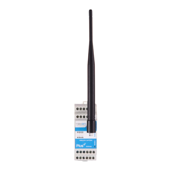
Wireless gateway
Hide thumbs
Also See for PLUS WGW420:
- Product manual (59 pages) ,
- Installation manual (44 pages) ,
- Installation manual (44 pages)

Related Manuals for Tekon PLUS WGW420


Summary of Contents for Tekon PLUS WGW420
- Page 1 PLUS WGW420 INSTALLATION GUIDE IG_PLUS_WGW420_E02A TEKON ELECTRONICS AVEIRO, PORTUGAL +351 234 303 320 +351 933 033 250 sales@tekonelectronics.com...
- Page 2 DUOS WIRELESS SYSTEM INSTALLATION GUIDE PLUS WGW420 WIRELESS GATEWAY INSTALLATION GUIDE Table of contents step WGW420 PLUS WIRELESS GATEWAY CONFIGURATION Pages 3 to 12 step WGW420 GATEWAY ANALOG OUTPUTS CONFIGURATION Pages 13 to 16...
- Page 3 step WGW420 PLUS WIRELESS GATEWAY CONFIGURATION...
- Page 4 PLUS WGW420 INSTALLATION GUIDE step WGW420 PLUS WIRELESS GATEWAY CONFIGURATION TEKON CONFIGURATOR SOFTWARE is only compatible with the Microsoft® Windows® Operating System. Connect the antenna to the Gateway. Wiring Connect the power supply and then the RS485-USB cable to the Gateway.
- Page 5 INSTALLATION GUIDE PLUS WGW420 step WGW420 PLUS WIRELESS GATEWAY CONFIGURATION Check device connection state by LED indication. Green LEDs permanently on Red LEDs permanently on WIRELESS GATEWA Y 10 Seconds to enter configuration mode Normal mode Open Tekon Configurator Software...
- Page 6 PLUS WGW420 INSTALLATION GUIDE step WGW420 PLUS WIRELESS GATEWAY CONFIGURATION Open the WGW420 PLUS Wireless Gateway device page. You can enter the device’s page in the following ways: 1st option: Click on “SMART TRANSMITTERS” in the left menu and then click on the WGW420 device.
- Page 7 INSTALLATION GUIDE PLUS WGW420 step WGW420 PLUS WIRELESS GATEWAY CONFIGURATION Load the “Port COM” corresponding to the WGW420 PLUS Wireless Gateway. NOTE: If the USB cable has already been connected before opening the device page, “Port COM” will appear in the list, otherwise you need to click on the “...
- Page 8 PLUS WGW420 INSTALLATION GUIDE step WGW420 PLUS WIRELESS GATEWAY CONFIGURATION Perform a power cycle on the Gateway. NOTE: After power up, you have 10 seconds to enter configuration mode by clicking on Connect button ( (while green LEDs are permanently on).
- Page 9 INSTALLATION GUIDE PLUS WGW420 step WGW420 PLUS WIRELESS GATEWAY CONFIGURATION The software will connect to the device. NOTE: If the software is unable to connect to the device, the status is displayed. If it hasn’t connected, go back to the previous steps and check the port COM.
- Page 10 PLUS WGW420 INSTALLATION GUIDE step WGW420 PLUS WIRELESS GATEWAY CONFIGURATION When the software connects to the device, the “Connected” message will be displayed. You can also verify configuration mode activation by checking LEDs on the gateway. Green LEDs performing scan animation...
- Page 11 INSTALLATION GUIDE PLUS WGW420 step WGW420 PLUS WIRELESS GATEWAY CONFIGURATION Configure the device fields and write by clicking on the “WRITE DEVICE” button. NOTE: The “WRITE DEVICE” button will only be active when there is a change to one of the editable fields, if there is no change it will be disabled.
- Page 12 PLUS WGW420 INSTALLATION GUIDE step WGW420 PLUS WIRELESS GATEWAY CONFIGURATION Click on the button ( ) to exit configuration mode and return the device to normal operating mode.
- Page 13 step WGW420 GATEWAY ANALOG OUTPUTS CONFIGURATION...
-
Page 14: Modbus Mode
PLUS WGW420 INSTALLATION GUIDE step GATEWAY ANALOG OUTPUTS Follow steps 06 and 07 of the PLUS Wireless Gateway Configuration. Tekon Configurator Software select MODBUS MODE >> ANALOG OUTPUTS Click the ( ) button and wait for the device to connect. - Page 15 INSTALLATION GUIDE PLUS WGW420 step GATEWAY ANALOG OUTPUTS Considering the transmitter configuration with Modbus Address=1, there is a Gateway Modbus Address Window corresponding to Modbus address window [0-19]. MB Add HOLDING REGISTERS - TRANSMITTERS DATA Description Address Serial Number (Transmitter Modbus Index-1) x 20+0...
- Page 16 PLUS WGW420 INSTALLATION GUIDE step GATEWAY ANALOG OUTPUTS Link the “Output Index” (Gateway) to Temperature Input 1 (Transmitter) and configure the “Modbus Address Link” according to the previous step. Set the minimum and maximum values and click on “Send Data”.
- Page 17 TEKON ELECTRONICS a brand of Bresimar Automação S.A. Avenida Europa, 460 Quinta do Simão 3800-230 Aveiro PORTUGAL Sales P.: +351 234 303 320 M.: +351 933 033 250 E.: sales@tekonelectronics.com Technical Support E.: support@tekonelectronics.com...
Need help?
Do you have a question about the PLUS WGW420 and is the answer not in the manual?
Questions and answers