Advertisement
Quick Links
PLUS TWPH-1UT
PLUS TWPH-1UT
PLUS TWPH-1UT
PLUS TWPH-1UT
PLUS TWPH-1UT
INSTALLATION GUIDE
INSTALLATION GUIDE
INSTALLATION GUIDE
TEKON ELECTRONICS AVEIRO, PORTUGAL
TEKON ELECTRONICS AVEIRO, PORTUGAL
P.:
M.:
P.:
+351 234 303 320
+351 234 303 320
M.:
+351 933 033 250
+351 933 033 250
E.:
E.:
sales@tekonelectronics.com
sales@tekonelectronics.com
IG_PLUS_TWPH-1UT_E01A
Advertisement

Related Manuals for Tekon PLUS TWPH-1UT


Summary of Contents for Tekon PLUS TWPH-1UT
- Page 1 PLUS TWPH-1UT PLUS TWPH-1UT PLUS TWPH-1UT PLUS TWPH-1UT INSTALLATION GUIDE INSTALLATION GUIDE INSTALLATION GUIDE IG_PLUS_TWPH-1UT_E01A TEKON ELECTRONICS AVEIRO, PORTUGAL TEKON ELECTRONICS AVEIRO, PORTUGAL +351 234 303 320 +351 234 303 320 +351 933 033 250 +351 933 033 250 sales@tekonelectronics.com sales@tekonelectronics.com...
-
Page 2: Table Of Contents
DUOS WIRELESS SYSTEM INSTALLATION GUIDE PLUS TWPH-1UT INSTALLATION GUIDE Table of contents step WGW420 PLUS WIRELESS GATEWAY CONFIGURATION Pages 3 to 11 step TWPH-1UT PLUS WIRELESS TEMPERATURE TRANSMITTER CONFIGURATION Pages 12 to 19 step WGW420 GATEWAY ANALOG OUTPUTS CONFIGURATION Pages 20 to 22... -
Page 3: Wgw420 Plus Wireless Gateway Configuration
step WGW420 PLUS WIRELESS GATEWAY CONFIGURATION... - Page 4 PLUS TWPH-1UT INSTALLATION GUIDE step WGW420 PLUS WIRELESS GATEWAY CONFIGURATION TEKON CONFIGURATOR SOFTWARE is only compatible with the Microsoft® Windows® Operating System. Connect the antenna to the Gateway. Wiring Connect the power supply and then the RS485-USB cable to the Gateway.
- Page 5 Green LEDs permanently on Red LEDs permanently on WIRELESS GATEWA Y 10 Seconds to enter configuration mode Normal mode Open Tekon Configurator Software and select PLUS >> Gateway >> Configuration Tekon Configurator software is free of charge and available at www.tekonelectronics.com...
- Page 6 PLUS TWPH-1UT INSTALLATION GUIDE step WGW420 PLUS WIRELESS GATEWAY CONFIGURATION Select serial port corresponding to WGW420 PLUS Wireless Gateway Click on the Rescan Ports button. Select corresponding Port name You can check device’s serial port name in “Device Manager” on Microsoft ® Windows® operating system.
- Page 7 INSTALLATION GUIDE PLUS TWPH-1UT step WGW420 PLUS WIRELESS GATEWAY CONFIGURATION Perform a power cycle on the Gateway. NOTE: After power up, you have 10 seconds to enter confi guration mode by clicking on Connect button ( (while green LEDs are permanently on).
- Page 8 PLUS TWPH-1UT INSTALLATION GUIDE step WGW420 PLUS WIRELESS GATEWAY CONFIGURATION The status string at the bottom of the software window provides feedback on ongoing operations. You can also verify configuration mode activation by checking LEDs on the gateway. Green LEDs performing...
- Page 9 INSTALLATION GUIDE PLUS TWPH-1UT step WGW420 PLUS WIRELESS GATEWAY CONFIGURATION Take note of device confi guration data available, namely: Modbus Address, Modbus Baudrate, Modbus Parity, Wireless Network ID Wireless Channel. NOTE: The wireless network connection between devices is ensured by setting the same Wireless Network ID and Wireless Channel parameters.
- Page 10 PLUS TWPH-1UT INSTALLATION GUIDE step WGW420 PLUS WIRELESS GATEWAY CONFIGURATION Modbus Communication Select Modbus tab of the Gateway and set the previously saved confi gurations. Ensure that Port name, Baudrate, Parity Modbus Address fi elds are the same as those obtained in confi guration mode.
- Page 11 INSTALLATION GUIDE PLUS TWPH-1UT step WGW420 PLUS WIRELESS GATEWAY CONFIGURATION NOTE: See WGW420 Datasheet to access LED indication information - page 4. Red LEDs permanently on LED flashes on each wireless communication WIRELESS GATEWA Y...
-
Page 12: Twph-1Ut Plus Wireless Temperature Transmitter Configuration
step TWPH-1UT PLUS WIRELESS TEMPERATURE TRANSMITTER CONFIGURATION... - Page 13 INSTALLATION GUIDE PLUS TWPH-1UT step TWPH-1UT PLUS WIRELESS TEMPERATURE TRANSMITTER CONFIGURATION Connect the antenna and sensor connectors to the TWPH-1UT PLUS Wireless Transmitter.. Connect the micro USB cable to the computer and then to TWPH-1UT PLUS Wireless Transmitter. Open a new window of...
- Page 14 PLUS TWPH-1UT INSTALLATION GUIDE step TWPH-1UT PLUS WIRELESS TEMPERATURE TRANSMITTER CONFIGURATION Click on Rescan Ports button. Select corresponding Port name You can check device’s serial port name in “Device Manager” on Microsoft® Windows® operating system.
- Page 15 INSTALLATION GUIDE PLUS TWPH-1UT step TWPH-1UT PLUS WIRELESS TEMPERATURE TRANSMITTER CONFIGURATION Click on Confi guration Mode ) button. When the TWPH-1UT Transmitter is in Confi guration Mode, all LEDs are active but with diff erent behaviours. LED permanently on LED fl ashing with 1...
- Page 16 PLUS TWPH-1UT INSTALLATION GUIDE step TWPH-1UT PLUS WIRELESS TEMPERATURE TRANSMITTER CONFIGURATION Configure Wireless Network ID Wireless Channel previously obtained from Gateway. The wireless connection between both devices is ensured by setting the same Wireless Network ID Wireless Channel parameters. Gateway Modbus Index will define the modbus registers window used to store information sent by the transmitter.
- Page 17 INSTALLATION GUIDE PLUS TWPH-1UT step TWPH-1UT PLUS WIRELESS TEMPERATURE TRANSMITTER CONFIGURATION Click on Sensor Input tab. Select the Sensor Type you will use.
- Page 18 PLUS TWPH-1UT INSTALLATION GUIDE step TWPH-1UT PLUS WIRELESS TEMPERATURE TRANSMITTER CONFIGURATION Click on Write button to update the Transmitter settings. Click on Read button to read the sensor and internal temperature. Click on Confi guration Mode ) button to exit from confi guration mode to normal operating mode.
- Page 19 INSTALLATION GUIDE PLUS TWPH-1UT step TWPH-1UT PLUS WIRELESS TEMPERATURE TRANSMITTER CONFIGURATION After clicking on Disconnect button, the device will permanently attempt to connect to a wireless network. If there is no communication, the red LED flashes slowly until the connection occurs or by 1 minute.
-
Page 20: Wgw420 Gateway Analog Outputs Configuration
step WGW420 GATEWAY ANALOG OUTPUTS CONFIGURATION... - Page 21 INSTALLATION GUIDE PLUS TWPH-1UT step GATEWAY ANALOG OUTPUTS Follow steps 06 and 07 of the PLUS Wireless Gateway Confi guration. Tekon Confi gurator Software select PLUS >> Gateway >> Analog Outputs menu Considering the transmitter confi guration with GTW Modbus Index=1, there is a Gateway Modbus Address Window corresponding to Modbus address window [0-19].
- Page 22 PLUS TWPH-1UT INSTALLATION GUIDE step GATEWAY ANALOG OUTPUTS Link Analog Output Index 1 (Gateway) to Analog Input 1 (Transmitter) and confi gure MB Add Link according to the previous step. Set minimum and maximum values and click on Write 4000 (4mA)
-
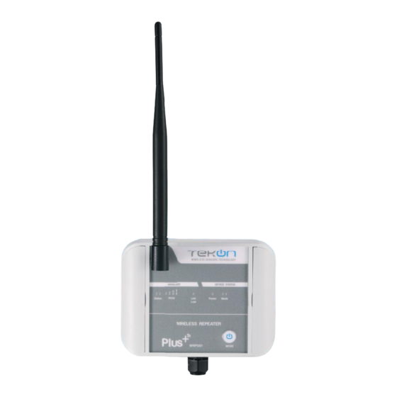
Page 23: Wrp001 Plus Wireless Repeater Configuration
step WRP001 PLUS WIRELESS REPEATER CONFIGURATION... - Page 24 PLUS TWPH-1UT INSTALLATION GUIDE step CONNECT AND CONFIGURE THE PLUS WIRELESS REPEATER Loosen the 4 screws of the case and oppen it. Connect a micro USB cable to the computer and then to WRP001 PLUS Wireless Repeater. Open a new window of...
- Page 25 INSTALLATION GUIDE PLUS TWPH-1UT step CONNECT AND CONFIGURE THE PLUS WIRELESS REPEATER Click on Rescan Ports button. Select corresponding Port name You can check device’s serial port name in “Device Manager” on Microsoft® Windows® operating system.
- Page 26 PLUS TWPH-1UT INSTALLATION GUIDE step CONNECT AND CONFIGURE THE PLUS WIRELESS REPEATER Click on Confi guration Mode ) button. ) button. permanently LEDs fl ashing until wireless connection is established ANALOG WIRELESS TRANSMITTER WIRELESS REPEATER permanently...
- Page 27 INSTALLATION GUIDE PLUS TWPH-1UT step CONNECT AND CONFIGURE THE PLUS WIRELESS REPEATER Confi gure Wireless Network ID Wireless Channel previously obtained from Gateway. Click on Write button to update Transmitter settings. Click on Confi guration Mode ) button to exit setup and resume normal operating mode.
- Page 28 PLUS TWPH-1UT INSTALLATION GUIDE step CONNECT AND CONFIGURE THE PLUS WIRELESS REPEATER permanently LEDs flashing until wireless connection is established permanently ANALOG WIRELESS TRANSMITTER WIRELESS REPEATER Connection to the Gateway established Connection to the Gateway not established...
-
Page 29: Site Survey
step SITE SURVEY MODE... - Page 30 PLUS TWPH-1UT INSTALLATION GUIDE step SITE SURVEY MODE Refers to following devices: TWP4AI Transmitter, TWP-4AI4DI1UT Transmitter, WRP001 Repeater TWPH-1UT Transmitter. Site survey mode is a tool that allows a quick wireless signal strength evaluation at the site of installation. It doesn’t require additional equipment or software.
- Page 31 INSTALLATION GUIDE PLUS TWPH-1UT step SITE SURVEY MODE Press and hold operations button for 3 seconds. Red and green LEDs will stay on. Blue LEDs indicate the signal strength. Operations button LED permanently on LED flashing RSSI communication level MEDIUM...
- Page 32 TEKON ELECTRONICS a brand of Bresimar Automação S.A. Avenida Europa, 460 Quinta do Simão 3800-230 Aveiro PORTUGAL Sales P.: +351 234 303 320 M.: +351 933 033 250 E.: sales@tekonelectronics.com Technical Support E.: support@tekonelectronics.com...
Need help?
Do you have a question about the PLUS TWPH-1UT and is the answer not in the manual?
Questions and answers