Copeland CC200 Quick Start Manual
Expansion module hardware and wiring
Hide thumbs
Also See for CC200:
- Installation and operation manual (106 pages) ,
- Quick start manual (8 pages) ,
- Quick start manual (4 pages)
Advertisement
Available languages
Available languages
Quick Links
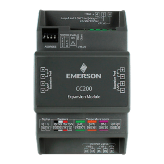
CC200 Expansion Module
Hardware and Wiring
Quick Start Guide
The CC200 Expansion Module is built with the
necessary onboard IO to add additional IO for modular
coil case designs or multi-evaporator
walk-in boxes.
CC200 Main Controller
CC200 Expansion Module
• One TRIAC for control of PWM (pulse width
modulation) EEV valve or one stepper motor control
for EEPR stepper or EEV stepper.
• One digital input: user-configurable purposes.
• One pressure input for suction pressure transducer.
• Three color-coded temperature inputs for discharge
air, return air, and defrost termination plus coil out
temperature.
• Expansion port connector for easy connection to
CC200 Main Controller.
Specifications
Powered From Expansion Port
Power
of CC200 Main Controller
Ambient Operating
14°F to 122°F (-10°C to 50°C)
Temperature
Storage Temperature
-40°F to 185°F (-40°C to 85°C)
Relative Humidity
20-85% RH; non-condensing
24VDC, max 20W PELV (Class 2
Power Supply
Source)
Type: 4 DIN Rail Mountable Rating:
Enclosure
UL 94V-0
Dimensions
110mm x 183mm (4 5/16" x 7 3/16")
Purpose of Control
Operating Control
DIN rail mounting control to be
Construction of
incorporated in Class I or Class II
Control
appliances
Rated Impulse Voltage
2500V
Pollution Degree
2
Over-voltage Category
II
Type of Action
1.C
Pulse Valve TRIAC
24/120/230VAC, 20W Max
12VDC, max 330mA/Phase (Class 2
Unipolar Valve
circuit)
12VDC, max 800mA
Bipolar Valve
(Class 2 circuit)
For Technical Support:
Call: 833-409-7505 or
Email: ColdChain.TechnicalServices@copeland.com
For the full user manual,
scan the QR code:
Mounting and Installation
Step 1: Determine if you need an Expansion Module.
a. An Expansion Module should be added for a second
or third coil. Each coil will have temp sensors and a
transducer and will be wired to the respective Expansion
Module.
Step 2: Addressing the Expansion Module.
a. Set the address of each Expansion Module using the
ON/OFF dip switch bank on the top left corner of the
hardware.
b. Expansion Module one must be set to address 1
(Position 1 up), Expansion Module two to address 2
(Position 2 up), Expansion Module three to address 3
(Positions 1 and 2 up).
Step 3: Install the Expansion Module.
a. Make sure power is OFF to the CC200 Main Controller.
Power will be restored in a later step.
b. Install Expansion Module 1 on the DIN rail adjacent
to the CC200's right side. The CC200 Expansion port
terminals V+, V-, LAN+ and LAN- will be aligned with
Expansion Module 1 Expansion port terminals. Slide
the Expansion Module into the CC200 Expansion port
so both device's Expansion port connectors fasten
together.
c. If Expansion Modules 2 and 3 are present, connect to
Expansion Module 1's Expansion port using the same
manner described in the above step.
No wiring is needed between the CC200 Main Controller and
CC200 Expansion Module. Power and communication are
sourced from the CC200 Expansion port and passed through
each Expansion Module Expansion port.
Step 4: Terminate sensors on the Expansion Module and refer
to the drawing and specifications in the CC200 manual for
terminal numbers and how to terminate.
a. Once all sensor terminations are complete and the
Expansion Module Expansion port is securely plugged
into the CC200 Expansion port, restore the 24VDC
supply power to the CC200 Main Controller. Once
connected, the Expansion Module PWR ON LED will
illuminate green indicating supply power is present.
The contents of this publication are presented for informational purposes
only and they are not to be construed as warranties or guarantees, express
or implied, regarding the products or services described herein or their
use or applicability. Copeland reserves the right to modify the designs or
specifications of such products at any time without notice. Responsibility
for proper selection, use and maintenance of any product remains solely
with the purchaser and end-user. ©2023 Copeland is a trademark of
Copeland LP.
026-4715 | R7 | V0923
copeland.com
Advertisement

Related Manuals for Copeland CC200


Summary of Contents for Copeland CC200
- Page 1 Type: 4 DIN Rail Mountable Rating: Enclosure Step 3: Install the Expansion Module. UL 94V-0 a. Make sure power is OFF to the CC200 Main Controller. Dimensions 110mm x 183mm (4 5/16” x 7 3/16”) Power will be restored in a later step.
- Page 2 24/120/230VAC, 20W Max l’utilisateur. TRIAC CC200 pour les numéros de borne et la manière de terminer. 12VDC, max 330mA/Phase (circuit • Une entrée de pression pour capteur de pression Une fois que toutes les terminaisons de capteur sont...
Need help?
Do you have a question about the CC200 and is the answer not in the manual?
Questions and answers