Sign In
Upload
Manuals
Brands
Copeland Manuals
Controller
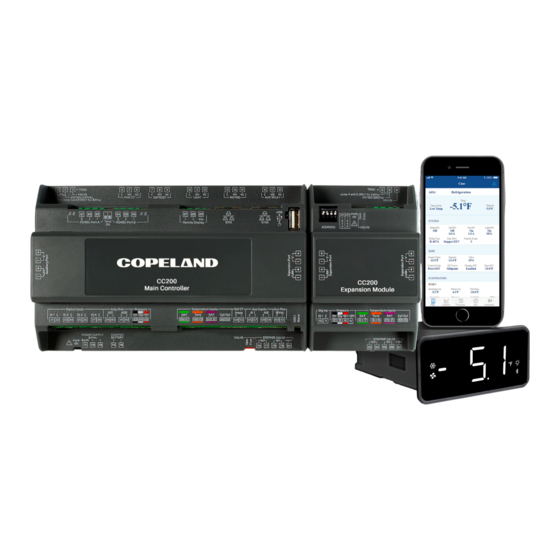
Case Controller 200
Copeland Case Controller 200 Manuals
Manuals and User Guides for Copeland Case Controller 200. We have
1
Copeland Case Controller 200 manual available for free PDF download: Installation And Operation Manual
Copeland Case Controller 200 Installation And Operation Manual (106 pages)
Brand:
Copeland
| Category:
Controller
| Size: 10 MB
Table of Contents
Table of Contents
3
Introduction
9
Overview of Capabilities
9
CC200 Overview
10
Expansion Module Overview
12
Case Display Overview
13
Powering and Wiring CC200
14
CC200 Power Wiring
15
CC200 Output Wiring
16
Fan Motors over 5A
16
CC200 Input Wiring
17
Coil Outlet Sensor Mounting
18
Pressure Transducer Mounting
19
EEV and EEPR Location
19
Expansion Module Remote Mounting
20
CC200 Stepper Valve Wiring
21
Bipolar Stepper Valve Connections
21
Wire Specifications for Extending Stepper Valves
21
CC200 Stepper Valve Specifications
22
Supported Stepper Valve List
22
PWM EEV Wiring
23
Pulse Width Modulation EEV Connections
23
CC200 Expansion Module Mounting and Installation
24
CC200 Expansion Module Specifications
25
CC200 Case Display Wiring
25
Control Logic Overview
27
Temperature Regulation
27
Refigeration Specific Controls
27
R744 (Co2)
27
System Overview
27
Superheat Optimization (Overfeed)
27
A2L Refrigerants
28
A2L Sensor
28
A2L Refrigerant Leak Notification
28
A2L Leak Mitigation Strategy
28
Superheat Regulation
28
Dual Temperature Cases
28
Case Lineup Management
28
Defrost Control
29
Manual Defrost
29
Pump down
29
Termination
29
Demand Defrost Control
29
Fan Control
29
Two Speed and Variable Speed Fans
30
Electric Evaporator Pressure Regulator (EEPR)
30
Pressure Mode
30
Floating SST Algorithm
30
Sensor Redundancy
31
Lighting Control
31
Door Switch
31
Shutdown Modes
31
Service Shutdown
31
Refrigerant Leak Shutdown
31
Night Shutdown
31
A2L Shutdown
32
Analog Inputs
32
Digital Inputs
32
Relay Outputs
33
Alarms
33
Analog Input Alarms
33
Fan Proof Alarm
33
Defrost Proof Alarm
33
Case Temperature Alarm
33
Communication Offline Alarms
33
Refrigerant Leak Alarm
33
CC200 Case Display
34
Display Overview
34
Unlock and Parameter Edits
34
Action Icons
36
Status Icons
36
The Bacnet Network
37
MS/TP-IP Router Topology
37
Bacnet IP with E3 Ethernet Ports
38
CC200 Bacnet IP Ethernet Cabling
40
Bacnet IP Ethernet Cable Recommended Cable Choices
40
Bacnet IP Ethernet Cable Recommended Connectors and Crimp Tools
40
Bacnet IP Ethernet Cable General Specifications
40
Bacnet Router RS485 Detail
41
Bacnet Router RS485 Specifications
42
Configuring Bacnet Settings on the CC200 Case Display
43
Router Devices
43
Non-Router Devices
44
Bacnet IP Devices for Connection to E3
44
Modbus Network
45
MODBUS Cable Requirements
45
Cat5E Cable Requirements
45
Configuring Modbus Settings on the CC200 Case Display
49
E2 Setup
50
Set up Network Ports and Bacnet Settings
50
Configure E2E Bacnet Settings
51
Add and Connect Case Controllers
51
Commissioning the Device in E2E
52
E2 Modbus Setup
53
Modbus Comm Port Setup
53
Add and Connect CC200 Devices
53
Commissioning the CC200 in E2E
54
E3 Setup - Bacnet and Modbus
55
Bacnet E3 Setup for MS/TP-IP Router Networks
55
Bacnet COM Port Setup
55
Bacnet E3 Setup for ETH 1 IP Network
56
Add and Connect Case Controllers
58
Modbus E3 Setup
60
Modbus COM Port Setup
60
Add and Connect Case Controllers
61
Cold Chain Connect Mobile Application
62
Download the Cold Chain Connect Application
62
Register the App
62
How to Activate Bluetooth® on the CC200 Case Display
63
Connecting to a Case
63
Information on the Case Tab
63
How to Set Parameters
64
Manual Defrost
64
Emergency Defrost
64
Calibrate Valve
65
Overrides
65
Restart the CC200
65
Real-Time Graphs
66
Viewing Alarms
66
Info
67
Disconnect from the Case
67
Select Connection
67
Configuring CC200 Parameters
68
Technical Specifications and Part Numbers
76
CC200 Case Controller Specifications
76
CC200 Power Supply Specifications
76
CC200 Case Expansion Module Specifications
77
CC200 Case Display Specifications
77
Part Numbers for Ordering
78
Appendix A: CC200 Parameters
79
Appendix B: Dimensions
102
Appendix C: Door Switch Mounting and Wiring Hinged Doors
103
Appendix D: Door Switch Mounting and Wiring Sliding Doors
104
Appendix E: 118-4101 Door Switch Dimensions
105
Advertisement
Advertisement
Related Products
Copeland 201-1160
Copeland 250-5000
Copeland 543-0175-00
Copeland 571-0106-00
Copeland 571-0107-00
Copeland 810-3074
Copeland 810-3199
Copeland 818-9010
Copeland Categories
Controller
Air Compressor
Measuring Instruments
Thermostat
Control Unit
More Copeland Manuals
Login
Sign In
OR
Sign in with Facebook
Sign in with Google
Upload manual
Upload from disk
Upload from URL