Table of Contents
Advertisement
Quick Links
Advertisement
Table of Contents

Related Manuals for Inovance GL20-2S485


Summary of Contents for Inovance GL20-2S485
- Page 1 *PS00009054A01*...
- Page 3 Preface ■ Introduction The GL20‑2S485 module provides two channels of RS485 communication and can be used together with AM300/AM500/AM400/AM600/AC700/AC800 series controllers and GL20 series communication interface module such as GL20‑RTU‑ECT. This guide describes the mechanical installation, electrical installation, fault diagnosis and programming examples of the product.
-
Page 4: Revision History
■ Access to the Guide This guide is not delivered with the product. You can obtain the PDF version in the following way: http://www.inovance.com Visit , go to Support > Download, search by keyword, ● and then download the PDF file. -
Page 5: Warranty
Damage or secondary damage caused by force majeure (natural disaster, ● earthquake, and lightning strike) The maintenance fee is charged according to the latest Price List of Inovance. If otherwise agreed upon, the terms and conditions in the agreement shall prevail. For details, see the Product Warranty Card. -
Page 6: Safety Instructions
4. Use this equipment according to the designated environment requirements. Damage caused by improper use is not covered by warranty. 5. Inovance shall take no responsibility for any personal injury or property damage caused by improper use. ■... -
Page 7: Installation
An emergency stop circuit, a protection circuit, a forward/reverse operation interlocked ● circuit, and a upper position limit and lower position limit interlocked circuit must be set in the external circuits of PLC to prevent damage to the machine. To ensure safe operation, for the output signals that may cause critical accidents, please ●... - Page 8 Prevent metal filings and wire ends from dropping into ventilation holes of the PLC ● during installation. Failure to comply may result in fire, fault and malfunction. Ensure there are no foreign matters on ventilation surface. Failure to comply may result ●...
- Page 9 Safety Recommendations In the position where the operator directly touches the machinery part, for example, ● where a machinery tool is loaded/unloaded, or where a machine runs automatically, manually‑operated devices or similar must be installed independently of the PLC to start or stop the automatic operation of the system.
-
Page 10: Product Information
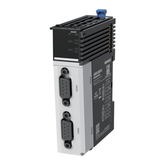
1 Product Information Model and Nameplate ① Product Information ③ Number of channels GL: General local module 2: Two channels ④ Module Type ② Serial Number 20: 20 series module S485: RS‑485 communication conversion Based on the above description of model number and nameplate, the relevant ordering data of this product is described in the following table. - Page 11 Components ‑ ‑...
- Page 12 Description Name ON: The module is Power / running Yellow ● in normal indicator green operation. Flashing quickly ● (200 ms interval): The module is addressed successfully. PR (POWER Flashing slowly +RUN) ● (1000 ms interval): The module is Signal ①...
- Page 13 Description Name ON: Data Running Green ● communication in indicator progress OFF: No data ● communication ON: Data Error indicator ● communication COM2 error. For ③ indicator troubleshooting, " Fault Diagnosis " on page 19 OFF: Data ● communication is normal Red: Digital Orange: Analog...
-
Page 14: General Specifications
Specifications ■ General Specifications Item Specification IP rating IP20 Dimensions (W x H x D) 24 mm x 100 mm x 75 mm Weight Approx. 89 g ■ Power Supply Specifications Item Specification Rated bus input voltage 5 VDC (4.75 VDC to 5.25 VDC) Rated bus input current 250 mA (typical@5 V) Rated terminal input voltage... -
Page 15: Environmental Specifications
Item Description Communication data refresh mode Free refresh Number of slaves Up to 31 slaves on a single port Communication distance Max. 1200 m. The higher the rate, the shorter the transmission distance. Isolation Termination resistor Not available. When the module is at either end of the network, an external matching resistor can be added. -
Page 16: Mechanical Installation
2 Mechanical Installation Mounting Dimensions The mounting dimensions (in mm) are shown in the figure below. Installation Method The module is mounted onto a DIN rail in conformity with IEC 60715 (width: 35 mm, thickness: 1 mm). The dimensions (unit: mm) are shown below. When installed on a DIN rail other than the recommended one (especially the one whose thickness is not 1.0 mm), the product will not fit in place as the mounting hook does not work. - Page 17 ■ Installing Modules Side-by-Side You can install multiple modules side by side with the help of top and bottom guides on the modules, as shown below. ■ Installing Module onto DIN Rail 1. Align the module with the DIN rail and push it in the direction indicated by the arrow until you hear a click, 2.
- Page 18 If the mounting hook is pressed down, it is locked. ● If the mounting hook is lifted up, it is unlocked. ● Press down the mounting hook to lock the module to the DIN rail. When the module is not installed on the rail, keep the mounting hook in the locked state.
- Page 19 ■ To removing the fan, do as follows: Pry the DIN rail mounting hook upwards with a tool such as slotted screwdriver, hold the protrusions and pull the module out straight forward, and then press down the top of the DIN rail mounting hook. ‑...
-
Page 20: Electrical Installation
3 Electrical Installation Terminal Assignment Pin No. Pin Signal ② RS485+ RS485‑ ⑦ ⑤ ‑ ①, ③, ④, ⑥, ⑧, ⑨ Enclosure ‑ ‑... -
Page 21: Fault Diagnosis
4 Fault Diagnosis When the ERR indicator of the module or the ERR indicator of the COM port is ON, it indicates that the module or the COM port encounters a fault. The module reports a fault code. You can get the fault code through the diagnostic data object dictionary value displayed on the "CoE Online"... - Page 22 ■ Module Fault Code Fault Code Fault Description Solution 0x5003 The isolated power supply of the Check the isolated power supply of module is faulty. the module ■ Module Channel Fault Code Module channel parameter configuration error ● Fault Code Fault Description Solution 0x2010...
- Page 23 Fault Code Fault Description Solution 0x6010 The transmit buffer of the module Decrease the length of data sent from channel is full. the module or increase the sending interval, or increase the baud rate setting. 0x6011 The receive buffer of the module Reduce the length of data sent to the channel is full.
-
Page 24: Programming Examples
InoProShop Programming Example (AM400&AM600&AC700&AC800) ■ Configuring GL20-2S485 as Modbus master 1. Add the GL20‑RTU‑ECT communication interface module. a. In the Devices pane, double‑click on Network Configuration, then check the EtherCAT Master checkbox to enable the PLC as an EtherCAT master. - Page 25 b. In the pop‑up window, double‑click on MODBUS master. c. In the Devices pane, double‑click on COM (Modbus Master) to open the Modbus master configuration page. ‑ ‑...
- Page 26 4. Add Modbus slave to the Modbus network. a. In the Devices pane, right‑click on COM (Modbus Master) and select Add COM slave. b. Double‑click on the added slave, then click the Modbus Slave Communication tab and set Unit ID and Timeout. ‑...
- Page 27 Note The AM400 and AM600 series controllers have a Slave Enable Variable (such ● as SM1001 in the figure above). Enable this variable before running the controller. The AC700 and AC800 series controllers do not have such variable and can ●...
- Page 28 5. After successful compiling, download the project and run it. ■ Configuring GL20-2S485 as Modbus slave 1. Add the GL20‑RTU‑ECT communication interface module. a. In the Devices pane, double‑click on Network Configuration, then check the EtherCAT Master checkbox to enable the PLC as an EtherCAT master.
- Page 29 b. In the pop‑up window, double‑click on MODBUS slave. c. In the Devices pane, double‑click on COM (Modbus Device) to open the Modbus slave configuration page. ‑ ‑...
- Page 30 4. After successful compiling, download the project and run it. ■ Configuring GL20-2S485 to apply free serial protocol 1. Add the GL20‑RTU‑ECT communication interface module. a. In the Devices pane, double‑click on Network Configuration, then check the EtherCAT Master checkbox to enable the PLC as an EtherCAT master.
- Page 31 3. Set the port of GL20‑2S485 module to free serial protocol. a. Right‑click on Device and select Add virtual device. c. In the pop‑up dialog, double‑click on free serial protocol. ‑ ‑...
- Page 32 Free Protocol Configuration page. 4. After successful compiling, download the project and run it. InoProShop Programming Example (AM300&AM500) 5.2.1 Adding GL20-2S485 Locally (AM300&AM500) ■ Adding the GL20-2S485 module In the Devices pane, double‑click on LocalBus Config under Network Configuration, then in the In\Output Module List pane, double‑click on the GL20‑...
- Page 33 ■ Configuring the GL20-2S485 module as Modbus master 1. Set the port of GL20‑2S485 module as Modbus master. a. After the GL20‑2S485 module is added, two COM ports are automatically generated: "COM_1 (Serial Port)" and "COM_2 (Serial Port)". b. Configure "COM_1 (Serial Port)" as a master by right‑clicking on "COM_1 (Serial Port)"...
- Page 34 3. Add Modbus slave to the Modbus network. a. In the Devices pane, right‑click on "Modbus_Master (Modbus Master)" and select Add Device. b. In the Add Device pop‑up, select "Modbus Slave" under Miscellaneous and click the Add Device button. You can add slaves based on the actual number of slaves in the network.
- Page 35 Click the Modbus Slave Communication Configuration tab, click Add and then add Modbus commands in the pop‑up dialog. ■ Configuring the GL20-2S485 module as Modbus slave 1. Set the port of GL20‑2SCOM module as Modbus slave. ‑ ‑...
-
Page 36: Table Of Contents
a. After the GL20‑2S485 module is added, two COM ports are automatically generated: "COM_1 (Serial Port)" and "COM_2 (Serial Port)". b. Configure "COM_2 (Serial Port)" as a slave by right‑clicking on "COM_2 (Serial Port)" under "Serial (Serial Interface)" and selecting Add Device... c. -
Page 37: After The Gl20-2S485 Module Is Added, Two Com Ports Are Automatically Generated: "Com_1 (Serial Port)" And "Com_2 (Serial Port)
■ Configure the GL20-2S485 module as free protocol serial port 1. Set the port of GL20‑2S485 module as Modbus free protocol serial port. a. After the GL20‑2S485 module is added, two COM ports are automatically generated: "COM_1 (Serial Port)" and "COM_2 (Serial Port)". - Page 38 2. In the Devices pane, double‑click on "COM_2 (Serial Port)", then click the COM Configuration tab and set the serial port communication parameters. 3. Set the free protocols in the Modbus network. In the Add Device pop‑up, double‑click on "Free_Protocol_Serial_Port" to open the Free Protocol Configuration pane where you can configure the corresponding parameters.
- Page 39 In the Devices pane, double‑click on Network Configuration, then check EtherCAT Master checkbox to enable the PLC as an EtherCAT master. b. In the right Network Devices List pane, go to EtherCAT Port > Inovance > Terminal Coupler, double‑click on "GL20‑RTU‑ECT_X.X.XX.X" under or drag and place it to the master.
- Page 40 2. Add the GL20‑2S485 module. a. In the Devices pane, double‑click on EtherCAT Config under Network Configuration to open the Hardware Configuration pane. b. In the In\Output Module List pane, double‑click on the GL20‑2S485 module, or drag and place it to the right side of the GL20‑RTU‑ECT module. Method 2: ●...
- Page 41 b. After the EtherCAT is enabled, "EtherCAT1 (EtherCAT Master SoftMotion)" is automatically added in the Devices pane. c. In the Devices pane, right‑click on "EtherCAT1 (EtherCAT Master SoftMotion)" and select Add Device... In the Add Device pop‑up, open "Terminal Coupler" folder, select "GL20‑RTU‑ECT_X.X.XX.X"...
- Page 42 Add Device button, or double‑click on "GL20‑2S485 (2 channels RS485 converter)". ■ Configuring the GL20-2S485 module as Modbus master 1. Set the port of GL20‑2S485 module as Modbus master. a. After the GL20‑RTU‑ECT_X.X.XX.X communication interface module and the GL20‑2S485 module are added, two COM ports are automatically generated:...
- Page 43 2. In the Devices pane, double‑click on "COM_1 (Serial Port)" to open the COM Configuration pane where you can configure the serial port of the master. 3. Add Modbus slave to the Modbus network. a. In the Devices pane, right‑click on "Modbus_Master (Modbus Master)" and select Add Device.
- Page 44 b. In the Add Device pop‑up, select "Modbus Slave" under Miscellaneous and click the Add Device button. You can add slaves based on the actual number of slaves in the network. c. In the left Devices pane, double‑click on the added "Modbus_Slave (Modbus Slave)", then click the Modbus Slave Communication tab and set Unit ID and Timeout.
-
Page 45: Configure "Com_2 (Serial Port)" As A Slave By Right-Clicking On "Com_2
■ Configuring the GL20-2S485 module as Modbus slave 1. Set the port of GL20‑2S485 module as Modbus slave. a. After the GL20‑RTU‑ECT_X.X.XX.X communication interface module and the GL20‑2S485 module are added, two COM ports are automatically generated: "COM_1 (Serial Port)" and "COM_2 (Serial Port)". -
Page 46: In The Devices Pane, Double-Click On "Com_2 (Serial Port)" To Open The Com Configuration Pane Where You Can Configure The Serial Port Of The Slave
2. In the Devices pane, double‑click on "COM_2 (Serial Port)" to open the COM Configuration pane where you can configure the serial port of the slave. 3. In the Devices pane, double‑click on the added "Modbus_Device (Modbus Slave)", then click the Modbus Slave Communication tab and set Unit ID and Time between Frames. - Page 47 ■ Configure the GL20-2S485 module as free protocol serial port 1. Set the port of GL20‑2S485 module as Modbus free protocol serial port. a. After the GL20‑RTU‑ECT_X.X.XX.X communication interface module and the GL20‑2S485 module are added, two COM ports are automatically generated: "COM_1 (Serial Port)"...
- Page 48 2. In the Devices pane, double‑click on "COM_2 (Serial Port)", then click the COM Configuration tab and set the serial port communication parameters. 3. Set the free protocols in the Modbus network. In the Add Device pop‑up, double‑click on "Free_Protocol_Serial_Port" to open the Free Protocol Configuration pane where you can configure the corresponding parameters.
- Page 49 ‑ ‑...
-
Page 50: Appendix 1: Response Time Of Module As A Virtual Slave
6 Appendix Appendix 1: Response Time of Module as A Virtual Slave When this module serves as a remote virtual slave through the GL20‑RTU‑ECT communication interface module, it takes a certain amount of time T to complete the response after receiving commands from the master. Ensure that the interval between commands sent by the master is greater than this time T, so that the module can reply the response data normally. - Page 51 115ms 135ms 165ms 225ms 365ms 160ms 180ms 210ms 270ms 410ms 205ms 225ms 255ms 315ms 455ms 10ms 245ms 265ms 295ms 355ms 495ms When the length of data sent from the serial port is 125 ● ECT Period 115200 57600 38400 19200 9600 \Baud Rate 35ms...
- Page 52 Note The above table shows the response time when the baud rate is between ● 9600 and 115200 and the time consumed for frame splitting and frame combining is the maximum. If there are strict and precise requirements for response time, it should be calculated according to data length, times of frame splitting and actual baud rate according to the following calculation formula.
- Page 53 Frame interval: Time between b2 and b3. The maximum value of processing time T2 of the PLC=5 * ECT period+frame interval. Time T3 is related to the ECT period, with a maximum value of T3=2 * ECT period. ● Time T4 is the time taken to send data through the serial port, in milliseconds. The ●...
-
Page 54: Appendix 2: Version Information
Time interval for Modbus master to send frames When an Inovance medium‑sized PLC is used as the master, the "Time between Frames" parameter (i.e. the time interval between frames sent by the Modbus master) under the Modbus Slave Configuration tab should be greater than the response time of the module serving as a virtual slave, as shown in the figure below.
Need help?
Do you have a question about the GL20-2S485 and is the answer not in the manual?
Questions and answers