Table of Contents
Advertisement
Quick Links
Advertisement
Table of Contents

Related Manuals for Inovance GL20-0800END


Summary of Contents for Inovance GL20-0800END
- Page 1 *PS00007034A00*...
-
Page 3: Standard Compliance
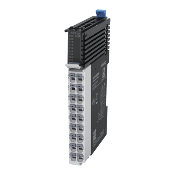
Preface ■ About this Guide GL20‑0800END series 8‑channel digital input module supports input of sink and source types, and can be used with Easy series products and GL20 series communication interface module such as GL20‑RTU‑ECT. This guide describes the mechanical installation, electrical installation and programming examples of the product. -
Page 4: Revision History
This guide is not delivered with the product. You can obtain the PDF version by the following method: www.inovance.com Log in to Inovance's website ( ), choose Support > Download, ● search by keyword, and then download the PDF file. - Page 5 Force majeure such as natural disasters, earthquake, lightning strike ● The maintenance fee is charged according to the latest Price List of Inovance. If otherwise agreed upon, the terms and conditions in the agreement shall prevail. For details, see Product Warranty Card.
-
Page 6: Safety Instructions
4. Use this equipment according to the designated environment requirements. Damage caused by improper use is not covered by warranty. 5. Inovance shall take no responsibility for any personal injuries or property damage caused by improper use. ■ Safety Levels and Definitions : Indicates that failure to comply with the notice will result in death or severe personal injuries. -
Page 7: Installation
An emergency stop circuit, a protection circuit, a forward/reverse operation interlocked ● circuit, and a upper position limit and lower position limit interlocked circuit must be set in the external circuits of PLC to prevent damage to the machine. To ensure safe operation, for the output signals that may cause critical accidents, please ●... - Page 8 Prevent metal filings and wire ends from dropping into ventilation holes of the PLC ● during installation. Failure to comply may result in fire, fault and malfunction. Ensure there are no foreign matters on ventilation surface. Failure to comply may result ●...
- Page 9 Maintenance & inspection must be carried out by personnel who have the necessary ● electrical training and experience. Do not touch the terminals while the power is on. Failure to comply may result in electric ● shock or malfunction. Disconnect all external power supplies of the system before cleaning the module. Failure ●...
-
Page 10: Product Information
1 Product Information Model Number and Nameplate ① Product ③ I/O Points ⑤ Module Type Voltage type ⑦ Information 8: 8 inputs E: Logic I/O D: 24 VDC GL: General expansion local module module ⑥ Output type ‑ ‑ ② Serial Number ④... - Page 11 Model Description Product Code Applicable Model GL20‑ GL20‑0800END 8‑channel digital 01440381 Easy series products and 0800END input (sink/source) module GL20 series communication interface modules such as GL20‑ RTU‑ECT Components Description Name Signal ON when the module is ① indicators in normal operation Flashes when the Yellow Power / running...
-
Page 12: Power Supply Specifications
Description Name Red: Digital output Orange: Analog output Color Gray: Digital input Green: Analog input ④ identification White: Blue: Other module Communication Specifications ■ Power supply specifications Item Specification Rated bus input voltage 5 VDC (4.75 VDC to 5.25 VDC) Rated bus input current 100 mA (typical@5 VDC) Rated terminal input voltage... -
Page 13: Software Specifications
Item Specification Isolation Input action display Input indicators are turned ON (via software control) when the inputs are in the driving state Input derating ■ Software specifications Item Specification Software input filter time Options include Without filter, 0.25 ms, 0.5 ms, 1ms (factory setting), 2 ms, 4 ms, 8 ms, 16 ms, and 32 ms. -
Page 14: Mounting Dimensions
2 Mechanical Installation Mounting Dimensions ■ Module The mounting dimensions (in mm) are shown in the figure below. ■ Cable Connection ‑ ‑... -
Page 15: Installation Method
Installation Method The module is mounted onto a DIN rail in conformity with EN 60715 (width: 35 mm, thickness: 1 mm). The dimensions (unit: mm) are shown below. ■ Installing Modules Side-by-Side You can install multiple modules side by side with the help of top and bottom guides on the modules, as shown below. - Page 16 Note: After the module is installed, the DIN rail mounting hook will automatically move downward to lock the module to the rail. If the hook does not move downward, press down the top of the hook to ensure that the module is installed in place. Mount an end plate on either side of the module assembly.
-
Page 17: Removing Module
■ Removing Module Pry the DIN rail mounting hook upwards with a tool such as slotted screwdriver, hold the protrusions and pull the module out straight forward, and then press down the top of the DIN rail mounting hook. ‑ ‑... -
Page 18: Cable Selection
3 Electrical Installation Cable Selection The cable lug and cable diameter included in the following table are only for reference. Material Applicable Cable Diameter Suzhou Yuanli Name Model Crimping Model Crimping Tool Tool E0308 0308 E0508 0508 Tubular 0.75 E7508 KST2000L 7508 YAC‑5... -
Page 19: Terminal Definition
Terminal Definition Left Indicator Left Signal Left Terminal Right Right Signal Right Terminal Indicator • • • • • • • • • ‑ ‑... -
Page 20: Terminal Wiring
Terminal Wiring ‑ ‑... -
Page 21: Programming Examples
4 Programming Examples The following is an example where the input voltage of channel 0 of the GL20‑ 0800END module is assigned to the corresponding variable, and AM600 is used as the main control module. 1. Add the GL20‑0800END module. 2. - Page 22 5. Define a variable D0 with the LD programming language. 6. After successful compiling, download the project and run it. ‑ ‑...
Need help?
Do you have a question about the GL20-0800END and is the answer not in the manual?
Questions and answers