Advertisement
Quick Links
User Guide
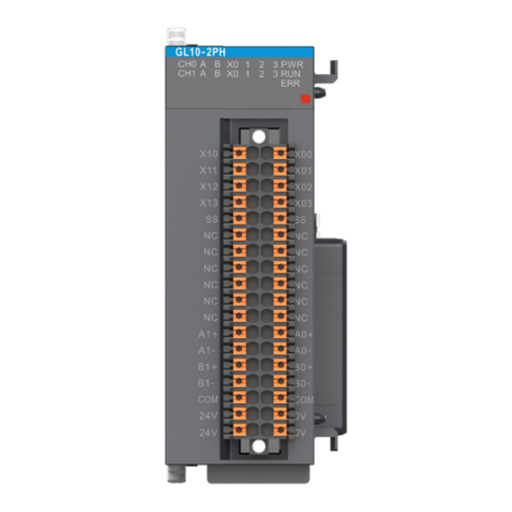
GL10-2PH High-Speed Differential
Pulse Positioning Module
Overview
Thank you for purchasing the GL10-2PH high-speed differential pulse positioning module developed and
manufactured independently by Inovance.
This product delivers 2*1 MHz high-speed differential output. It supports multiple pulse output modes, including
direction + pulse (required) or CW + CCW. It also supports homing positioning and left and right limiting. This
product is a perfect solution for sophisticated manufacture industries which involves a large number of axes, such
as mobile phone manufacture and TP. This guide describes the specifications, characteristics and using methods
of the product. Please read this guide carefully before using to ensure safe usage. Visit our website
com) for the latest version of the guide.
Safety Instructions
Safety Precautions
1. Before installing, using, and maintaining this equipment, read the safety information and precautions
thoroughly, and comply with them during operations.
2. To ensure the safety of humans and equipment, follow the signs on the equipment and all the safety instructions
in this user guide.
3. The "CAUTION" , "WARNING" and "DANGER" signs are only supplements to the safety instructions.
4. Use this equipment according to the designated environment requirements. Damage caused by improper usage
is not covered by warranty.
5. Inovance shall take no responsibility for any personal injuries or property damage caused by improper usage.
Safety Levels and Definitions
: Indicates that failure to comply with the notice may result in severe personal injuries or even death.
WARNING
: The "CAUTION" sign indicates that failure to comply with the notice may result in minor or moderate
CAUTION
personal injury or damage to the equipment.
Please keep this guide well so that it can be read when necessary and forward this guide to the end user.
During control system design
WARNING
◆ Provide a safety circuit outside the PLC so that the control system can still work safely once external power failure or
PLC fault occurs.
◆ Add a fuse or circuit breaker because the module may smoke or catch fire due to long-time overcurrent caused by
operation above rated current or load short-circuit.
CAUTION
◆ An emergency stop circuit, a protection circuit, a forward/reverse operation interlocked circuit, and a upper position
limit and lower position limit interlocked circuit must be set in the external circuits of PLC to prevent damage to the
machine.
◆ To ensure safe operation, for the output signals that may cause critical accidents, please design external protection
circuit and safety mechanism;
◆ Once PLC CPU detects abnormality in the system , all outputs may be closed; however, when a fault occurs in the
controller circuit, the output may not be under control. Therefore, it is necessary to design an appropriate external
control circuit to ensure normal operation;
◆ If the PLC output units such as relays or transistors are damaged, the output may fail to switch between ON and OFF
states according to the commands;
◆ The PLC is designed to be used in indoor electrical environment (overvoltage category II). The power supply must have
a system-level lightning protection device, assuring that overvoltage due to lightning shock cannot be applied to the
PLC power supply input terminals, signal input terminals and output terminals and so forth, so as to avoid damage to
the equipment.
WARNING
◆ Installation must be carried out by the specialists who have received the necessary electrical training and understood
enough electrical knowledge.
◆ Disconnect all external power supplies of the system before removing/installing the module. Failure to do so may
result in electric shock, module fault or malfunction.
◆ Do not use the PLC where there are dust, oil smoke, conductive dust, corrosive or combustible gases, or exposed to
high temperature, condensation, wind & rain, or subject to vibration and impact. Electric shock, fire and malfunction
may also result in damage or deterioration to the product.
◆ The PLC is open-type equipment that must be installed in a control cabinet with lock (cabinet housing protection
>IP20). Only the personnel who have received the necessary electrical training and understood enough electrical
knowledge can open the cabinet.
CAUTION
◆ Prevent metal filings and wire ends from dropping into ventilation holes of the PLC during installation. Failure to
comply may result in fire, fault and malfunction.
◆ Ensure there are no foreign matters on ventilation surface. Failure to comply may result in poor ventilation, which may
cause fire, fault and malfunction.
*19011285A01*
◆ Ensure the module is connected to the respective connector securely and hook the module firmly. Improper
installation may result in malfunction, fault or fall-off.
19011285 A01
WARNING
◆ Wiring must be carried out by personnel who have received the necessary electrical training and understood enough
electrical knowledge.
◆ Disconnect all external power supplies of the system before wiring. Failure to comply may result in electric shock,
module fault or malfunction.
1
◆ Install the terminal cover attached to the product before power-on or operation after wiring is completed. Failure to
comply may result in electric shock
◆ Perform good insulation on terminals so that insulation distance between cables will not reduce after cables are
connected to terminals. Failure to comply may result in electric shock or damage to the equipment.
CAUTION
◆ Prevent dropping metal filings and wire ends drop into ventilation holes of the PLC at wiring. Failure to comply may
result in fire, fault and malfunction.
◆ The external wiring specification and installation method must comply with local regulations. For details, see the wiring
section in this guide.
◆ To ensure safety of equipment and operator, use cables with sufficient diameter and connect the cables to ground
reliably.
◆ Ensure that all cables are connected to the correct interface. Failure to comply may result in module and external
equipment fault.
◆ Tighten bolts on the terminal block in the specified torque range. If the terminal is not tight, short-circuit, fire or
malfunction may be caused. If the terminal is too tight, fall-off, short-circuit, fire or malfunction may be caused.
(www.inovance.
◆ If the connector is used to connect with external equipment, perform correct crimping or welding with the tool
specified by manufacturer. If connection is in poor contact, short-circuit, fire or malfunction may be caused.
◆ A label on the top of the module is to prevent foreign matters entering the module. Do not remove the label during
wiring. Remember to remove it before system operation, facilitating ventilation.
◆ Do not bundle control wires, communication wires and power cables together. They must be run with distance of more
than 100 mm. Otherwise, noise may result in malfunction.
◆ Select shielded cable for high-frequency signal input/output in applications with serious interference so as to enhance
system anti-interference ability.
WARNING
◆ Maintenance & inspection must be carried out by personnel who have the necessary electrical training and experience.
◆ Do not touch the terminals while the power is on. Failure to comply may result in electric shock or malfunction.
◆ Disconnect all external power supplies of the system before cleaning the module or re-tightening screws on the terminal
block or screws of the connector. Failure to comply may result in electric shock.
◆ Disconnect all external power supplies of the system before removing the module or connecting/removing the
communication wirings. Failure to comply may result in electric shock or malfunction.
CAUTION
◆ Get with the guide and ensure safety before online modification, forcible output, and RUN/STOP operation.
◆ Disconnect the power supply before installing/removing the extension card.
CAUTION
◆ Treat scrapped module as industrial waste. Dispose the battery according to local laws and regulations.
Product Information
■ Model Number and Nameplate
Installation
Wiring
Operation and Maintenance
Disposal
2
Figure 1 Description of model number and nameplate
Model
Category
For local bus expansion, 2 high-speed differential output
GL10-2PH
Local I/O module
pulse positioning modules, output frequency 1 MHz, 8
ordinary inputs
■ External Interface
No.
Interface Name
PWR
Power indicator
Normal operation
State indicator
RUN
indicator
ERR
Fault indicator
①
CH0/1
Indicator
Pulse+direction
Signal indicator
A/B
Indicator
X0-X3
Digital input indicator
Local expansion
②
module back-end
Connect back-end module, not supporting hot plugging
interface
③
User terminal
Pulse output terminal, see "Electrical Design Reference"
Front-end
④
interface of local
Connects front-end module, not supporting hot plugging
expansion module
■ General Specifications
Item
Rated operating voltage
24 VDC (20.4 VDC to 28.8 VDC) (–15% to +20%)
Output channel
User terminal
36-pin leaf spring terminal, for both I/O and power supply
3
Applicable
Description
Model
H3U series
Function
ON when power supply is
Green
switched on
ON when power supply is
Green
switched on
Red
ON when the module is faulty
On when channel 0/1 is ready
Green
to output
Green
--
On when the input signal is
Green
active
Specifications
2
Advertisement

Subscribe to Our Youtube Channel
Related Manuals for Inovance GL10-2PH


Summary of Contents for Inovance GL10-2PH
- Page 1 ◆ Disconnect all external power supplies of the system before cleaning the module or re-tightening screws on the terminal 5. Inovance shall take no responsibility for any personal injuries or property damage caused by improper usage. block or screws of the connector. Failure to comply may result in electric shock.
- Page 2 ◆ Remove the insulation of the cable so that a length of 11–14 mm of the conductor is exposed, and put the cable The maintenance fee is charged according to the latest Maintenance Price List of Inovance. through a cable marking sleeve.
Need help?
Do you have a question about the GL10-2PH and is the answer not in the manual?
Questions and answers