Table of Contents

Related Manuals for Inovance GR10-EC-6SW


Summary of Contents for Inovance GR10-EC-6SW
- Page 1 GR10-EC-6SW 6-Port EtherCAT Branch Module User Guide Suzhou Inovance Technology Co., Ltd Address: No.16 Youxiang Road, Yuexi, Wuzhong District, Suzhou *19011256A01* Service hotline: 4000-300124 Website: http://www.inovance.com 19011256A01...
-
Page 2: Revision History
You can obtain the latest version on our website www.inovance.com. Reader This guide is intended for users who use or understand Inovance PLC products, including: electrical engineers, software engineers, and system engineers. Cautions for New User For the users who use this product for the first time, read the manual carefully. - Page 3 5. Inovance shall take no responsibility for any personal injuries or property damage caused by improper usage. ■ Safety Levels and Definitions : Indicates that failure to comply with the notice may result in severe WARNING personal injuries or even death.
- Page 4 Installation WARNING ◆ Installation must be carried out by the specialists who have received the necessary electrical training and understood enough electrical knowledge. ◆ Disconnect all external power supplies of the system before removing/installing the module. Failure to do so may result in electric shock, module fault or malfunction. ◆...
- Page 5 CAUTION ◆ Prevent dropping metal filings and wire ends drop into ventilation holes of the PLC at wiring. Failure to comply may result in fire, fault and malfunction. ◆ The external wiring specification and installation method must comply with local regulations. For details, see the wiring section in this guide.
-
Page 6: Product Information
1 Product Information Model Number and Nameplate GR10-EC-6SW 6-channel General Module EtherCAT Figure 1 Description of model number and nameplate Applicable Model Category Description Model Remote EtherCAT Remote EtherCAT branch module, Refer to the GR10-EC-6SW branch 1 input, 5 outputs... -
Page 7: External Interface
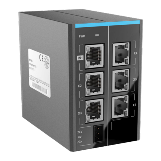
External Interface Figure 2 Module interfaces Interface Name Function ON when power supply is switched ① Power indicator PWR Green EtherCAT input Port1, EtherCAT output interface for connecting ② interface front-end EtherCAT master Port2, EtherCAT output interface for connecting back-end EtherCAT slaves Port3: EtherCAT output interface for connecting back-end EtherCAT slaves EtherCAT Output... -
Page 8: General Specifications
General Specifications Item Specifications Rated operating voltage 24 VDC (20.4 VDC to 28.8 VDC) (–15% to +20%) Internally consumed current Approx. 160 mA Communication protocol EtherCAT industrial real-time bus protocol EtherCAT channel 1 input and 5 outputs Max. comm. speed 100 Mbps Standard network port with Cat 5e network Network port/network cable... -
Page 9: Mounting Dimensions
2 Mechanical Design Reference Mounting Dimensions 88.5 53.2 97.5 Figure 3 Mounting dimensions diagram (in mm) 3 Electrical Design Reference Cable Preparation Figure 4 EtherCAT cable preparation Use Cat 5e shielded twisted pair (STP) cables, with injection molded and iron shelled connector. -
Page 10: Communication Wiring
■ Signal pins Signal Signal Direction Signal Description Output Data transmission+ Output Data transmission- Input Data reception+ Not used Not used Input Data reception– Not used Not used ■ Length requirements: According to FastEthernet technology, when an EtherCAT bus is used, the length of the cable between the devices must not exceed 100 meters. - Page 11 module horizontally. ■ Wiring of the communication system The EtherCAT branch module can connect multiple EtherCAT slave devices. The system wiring diagram is shown below: Figure 5 Wiring of the communication system...
- Page 12 To protect the communication cable from any tension and to ensure communication stability, fix the cable end which is near the device before EtherCAT communication. NOTE Configuration and use 1) When using this branch device, run all EtherCAT slaves (including the two stations of this branch device) with an alias, so that an abnormal branch will not affect the others.
-
Page 13: Warranty Agreement
If there is any failure or damage to the product, correctly fill out the Product Warranty Card. The maintenance fee is charged as the latest Maintenance Price List of Inovance. The Product Warranty Card is not re-issued. Keep the card and present it to the maintenance personnel when seeking maintenance.
Need help?
Do you have a question about the GR10-EC-6SW and is the answer not in the manual?
Questions and answers