Table of Contents
Advertisement
Advertisement
Table of Contents

Related Manuals for Inovance GL20-RTU-ECT


Summary of Contents for Inovance GL20-RTU-ECT
- Page 1 *PS00004985A01*...
-
Page 3: Revision History
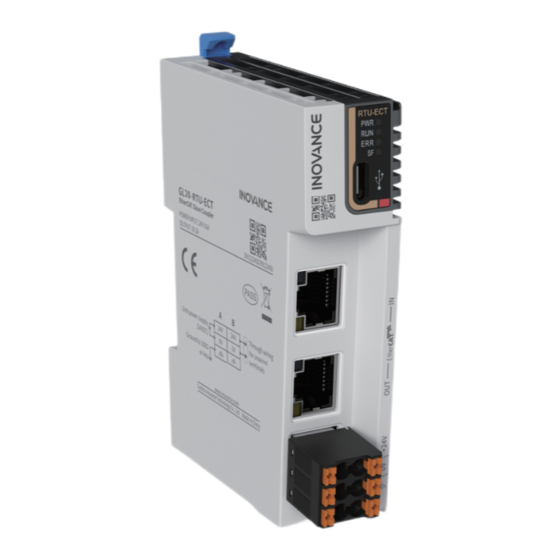
GL20‑RTU‑ECT series EtherCAT communication interface module This product features support for EtherCAT communication and auto scanning function and is applicable to Inovance and third‑party EtherCAT master such as PLC and boards. One EtherCAT communication interface module can connect up to 16 GL20 I/O modules. - Page 4 Force majeure such as natural disasters, earthquake, lightning strike ● The maintenance fee is charged according to the latest Price List of Inovance. If otherwise agreed upon, the agreed terms and conditions shall prevail. For details, see Product Warranty Card.
-
Page 5: Safety Instructions
4. Use this equipment according to the designated environment requirements. Damage caused by improper use is not covered by warranty. 5. Inovance shall take no responsibility for any personal injuries or property damage caused by improper use. ■ Safety Levels and Definitions : Indicates that failure to comply with the notice will result in severe personal injuries or even death. -
Page 6: Installation
An emergency stop circuit, a protection circuit, a forward/reverse operation interlocked ● circuit, and a upper position limit and lower position limit interlocked circuit must be set in the external circuits of PLC to prevent damage to the machine. To ensure safe operation, for the output signals that may cause critical accidents, design ●... - Page 7 Prevent metal filings and wire ends from dropping into ventilation holes of the PLC ● during installation. Failure to comply may result in fire, fault and malfunction. Ensure there are no foreign matters on ventilation surface. Failure to comply may result ●...
- Page 8 Maintenance & inspection must be carried out by personnel who have the necessary ● electrical training and experience. Do not touch the terminals while the power is on. Failure to comply may result in electric ● shock or malfunction. Disconnect all external power supplies of the system before cleaning the module or re‑ ●...
-
Page 9: Product Information
Based on the above description of model number and nameplate, the relevant ordering data of this product is described in the following table. Model Description Product Code Applicable Model GL20‑RTU‑ECT GL20‑RTU‑ECT EtherCAT 01440286 Inovance and third‑ communication interface party EtherCAT master module such as PLC and boards. ‑ ‑... - Page 10 Components The following describes the terminals and interfaces of the module. ‑ ‑...
- Page 11 Interface Description Name Power Green ON when power supply is indicator switched on ECT module is in INIT state Blinking (green) ECT module is in state Pre‑ Operational Running state Single flash ECT module is in state Safe‑ indicator (green) Operational ON (green) ECT module is in state...
-
Page 12: Power Supply Specifications
Specifications ■ Power supply specifications Item Specification Rated terminal input voltage 24 VDC (20.4 VDC to 28.8 VDC) Rated terminal input current 0.6 A (typical@24 V) Rated bus output voltage 5 VDC (4.75 VDC to 5.25 VDC) Rated bus output current 2 A (typical@5 V) Power output derating 85% derating at 55°C (the output current... -
Page 13: Environmental Specifications
Environmental Specifications Item Specification Ambient operating –20°C to 55°C temperature Ambient operating <95% RH, non‑condensing humidity Atmosphere Must be free from corrosive gases Ambient storage –20°C to 60°C (<90% RH, non‑condensing) temperature Altitude 2,000 m max. (80 kPa) Pollution degree 2 or less Noise immunity 2 kV on power supply line (Conforms to IEC 61000‑4‑4) -
Page 14: Mounting Dimensions
2 Mechanical Installation Mounting Dimensions ■ Module The mounting dimensions (in mm) are shown in the figure below. ■ Cable Connection ‑ ‑... -
Page 15: Installation Method
■ End Cover Installation Method ■ Installing Modules Side-by-Side Before installing the module, remove the end cover in the direction indicated by the arrow, as shown below. You can install multiple modules side by side with the help of top and bottom guides on the modules, as shown below. - Page 16 ■ Installing Module onto DIN Rail You can install the module onto a DIN rail. Align the module with the DIN rail and push the module in the direction indicated by the arrow until you hear a click, as shown below. Note: After the module is installed, the DIN rail mounting hook will automatically move downward to lock the module to the rail.
-
Page 17: Removing Module
■ Removing Module Pry the DIN rail mounting hook upwards with a tool such as slotted screwdriver, and then pull the module away from the DIN rail to remove it. ‑ ‑... -
Page 18: Cable Selection
3 Electrical Installation Cable Selection ■ Communication Wiring EtherCAT bus communication adopts shielded Ethernet cables for data transmission, without short circuit, misalignment and poor contact. The length of cables between devices cannot exceed 100m; otherwise, signal attenuation will occur and affect normal communication. -
Page 19: External Interface Specifications
■ External Interface Specifications Interface Interface Cable Type/ Description Terminals Specification Type Name Maximum Length EtherCAT EtherCAT Shielded EtherCAT RJ45 x 2 100 Mbps interface network communica‑ (100Base‑TX) cable, 100 m tion port Power supply 24 V input 3‑core 24 V power 6‑pin 24 V/1 A unshielded... -
Page 20: Fault Diagnosis
4 Fault Diagnosis LED indicator Meaning Solution No connection between EtherCAT Check configuration and master and slave parameter assignment; Check the communication address Check that the length and other specifications of the network cable are as specified. EtherCAT slave is in a state other Check slave configuration for any Blinking than state OPERATIONAL... -
Page 21: Programming Examples
5 Programming Examples 1. Create a project and perform hardware configuration. 2. Click Add Device. 3. After the module is added, configure the module parameters, download the project after compiling and run it. ‑ ‑... - Page 22 Module Together with Other GL20 Series Modules 1. Go to Toolbox > Ethercat Device > Inovance Device > Terminal Coupler, and double‑click GL20‑RTU‑ECT to add it. 2. Go to Project Manager > Config > EtherCAT, you can see the added coupler.
- Page 23 3. Double‑click the GL20‑RTU‑ECT device, click Slot Configuration, select the module you want to add and then click Add/Change. 4. Click Variable_Table and define the variables. ‑ ‑...
- Page 24 5. Click I/O Funtional Mapping and bind the define variables. 6. Compile the program. 7. After successful compiling, download the project and run it. ‑ ‑...
Need help?
Do you have a question about the GL20-RTU-ECT and is the answer not in the manual?
Questions and answers