Table of Contents
Advertisement
Quick Links
Advertisement
Table of Contents
Troubleshooting

Subscribe to Our Youtube Channel
Related Manuals for Inovance PA 8000 LW


Summary of Contents for Inovance PA 8000 LW
- Page 1 PA 8000 LW Installation instructions CNC control unit...
- Page 2 Inovance Technology Europe GmbH Gottlieb-Daimler-Str. 17/2 74385 Pleidelsheim Germany Telephone: +49-7144-899-0 Fax: +49-7144-899-299 E-mail: info@powerautomation.com Internet: www.powerautomation.com Original installation instructions Variante: PA 8000 LW STD SDI-AN / PA 8000E LW STD SDI-AN Version 4.0 © 2019 Inovance Technology Europe GmbH 13.09.2019...
-
Page 3: Table Of Contents
PA 8000 LW CNC control unit Table of contents Table of contents General information............. 7 Information on this manual.......... 7 Explanation of symbols..........7 Limitation of liability............9 Copyright..............9 Warranty terms............9 Customer service............10 Safety.................. 11 Customer's responsibility........... 11 Personnel requirements.......... - Page 4 PA 8000 LW CNC control unit Table of contents 3.3.1.4 RMS encoder wiring example....... 31 3.3.2 Analog Outputs............32 3.3.2.1 Output interfaces..........32 3.3.2.2 Output characteristics........... 33 3.3.2.3 Output schematic..........34 3.3.2.4 Output Monitor............35 3.3.2.5 Analog axes wiring example......... 35 3.3.3...
- Page 5 PA 8000 LW CNC control unit Table of contents Prerequisites and preparations........87 5.1.1 General requirements..........87 5.1.2 Electrical cabinet structural requirements....88 5.1.3 Cabinet temperature..........88 Mounting the control unit in a cabinet......89 Installing analog axes..........91 5.3.1 Analog axes wiring example........
- Page 6 PA 8000 LW CNC control unit Table of contents 13.09.2019 | 6...
-
Page 7: General Information
PA 8000 LW CNC control unit General information 1 General information 1.1 Information on this manual General Information This installation manual provides important information on how to work with the control unit safely and efficiently. The installation manual is part of the control unit, must always be kept in the control unit's direct proximity and should be available for the personnel at any time. - Page 8 PA 8000 LW CNC control unit General information NOTICE! … indicates a potentially hazardous situation which, if unavoidable, may result in property damage. … emphasizes useful hints and recommendations as well as information for efficient and trouble-free operation. Special Safety Notes...
-
Page 9: Limitation Of Liability
Apart from this, the obligations agreed upon in the delivery con- tract, the general terms and conditions, and the delivery conditions of Inovance and the legal regulations valid at the time of contract apply. We reserve the right to make technical modifications in order to improve usability. -
Page 10: Customer Service
For information on whom to contact by phone, fax, e-mail or via the internet, see Inovance's address on page 2. Additionally, Inovance staff is always interested in receiving new information and experiences resulting from the use of our products, which could be of great value for future improvements. -
Page 11: Safety
PA 8000 LW CNC control unit Safety 2 Safety 2.1 Customer's responsibility The control unit is used for commercial purposes. The operating company is thus subject to the legal obligations concerning indus- trial safety. The safety, accident prevention and environmental protection regu-... -
Page 12: Personnel Requirements
PA 8000 LW CNC control unit Safety 2.2 Personnel requirements 2.2.1 Qualifications WARNING! Danger of injury in case of insufficient qualifi- cation! Improper operation can lead to severe personal injuries and/or material damage. – Only those persons who have been specified in... -
Page 13: Unauthorized Persons
The control unit is to be used exclusively to control CNC machines of a supported number of axes which are in accordance with the types cleared by Inovance. Prerequisite for the intended use of the control unit is proper configuration as described in the installation manuals provided by Inovance. -
Page 14: Unintended Use
PA 8000 LW CNC control unit Safety The operator is solely responsible for all damage resulting from unintended use. 2.4 Unintended use Unintended Use WARNING! Beware of unintended use! – In particular, avoid using the control unit for the following purposes as these are regarded as not intended: –... -
Page 15: Specific Dangers
PA 8000 LW CNC control unit Safety ESD safety shoes for protection of components susceptible to electrostatic discharge. Wear the ESD safety shoes to protect electrostatic-discharge-sen- sitive devices due to inadequate derivative electrostatic energy. Ear protection for protection of the ears during the work. Wear the ear protection always until the work is finished. - Page 16 PA 8000 LW CNC control unit Safety DANGER! Uncontrolled operation due to improper instal- lation and configuration! The control unit's safety relay must be properly integrated into the CNC machine emergency stop chain. Improper wiring and configuration of the safety relay may result in uncontrolled operation of the CNC machine and in consequence may lead to irreversible personal injuries or death.
-
Page 17: Safety Devices
PA 8000 LW CNC control unit Safety 2.7 Safety devices Safety DANGER! Malfunctioning safety devices may pose a fatal risk! Safety devices must be intact and properly inte- grated into the control unit's configuration and soft- ware in order to guarantee safety. -
Page 18: Cnc Ready' Signal - Emergency Stop Interlocking
Injuries due to uncontrolled operation! An inactive 'CNC Ready' signal represents a safety related situation. The "CNC Ready" relay is switched off when the Inovance CNC control unit is in a situation where the axes' movements are not controlled. As the axes may continue to move in an uncon- trolled manner, the contacts of the "CNC Ready"... -
Page 19: Power Ok' Signal
PA 8000 LW CNC control unit Safety 2.8.2 'Power ok' signal The "Power ok" relay is triggered by the hardware monitoring of the internal supply voltages and the temperature sensor. The "Power ok" relay is switched off when the power supplies do not match the allowed range or the internal temperature is too high. -
Page 20: Data Safety
Ensure that backups are updated manually in case of modifi- cations to the configuration. 2.10.2 System protection Initial State Automated regular anti-virus scanning and manual scanning of files copied to the control unit are advised by Inovance as needed. 13.09.2019 | 20... -
Page 21: Registry Protection
Therefore registry protection and backup are prerequi- sites for proper control unit operation. A registry backup and recovery tool is preinstalled by Inovance on every control unit. Instructions... -
Page 22: Environmental Protection
Electronic Components Electronic components are considered special waste. They must be properly disposed of. Inovance will accept the control unit to properly dispose of its com- ponents upon decommissioning. 2.12 Labels The following labels are attached to the control unit. - Page 23 PA 8000 LW CNC control unit Safety Overview The labels listed hereunder are located at the positions shown in Fig. 1. Fig. 1: Label positions Material Warranty seal Type Plate License Operating system Type Plate The type plate includes the following information:...
- Page 24 PA 8000 LW CNC control unit Safety Operating System Product Key The label affixed to the side of the control unit next to the type plate provides the operating system's product key. CAUTION! If the label with the operating systems's product...
-
Page 25: Design And Function
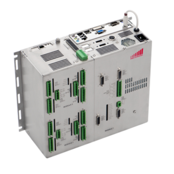
PA 8000 LW CNC control unit Design and function 3 Design and function 3.1 Overview Top View Fig. 4: Modules PC connectors [all models] Module 2416EL (1) [all models] Module 2416EL (2) [all models] Module 4AXLX [models with analog axes only]... -
Page 26: Brief Description
PA 8000 LW CNC control unit Design and function Model Configurations The PA 8000 LW is shipped in three different models containing the following modules and interfaces. Model Description PC con- Module 2416EL Module 4AXLX nectors PA 8000 LW SDI and analog... -
Page 27: Module 4Axlx
PA 8000 LW CNC control unit Design and function 3.3 Module 4AXLX Overview Not included in all models This module and its interfaces are only included in models with analog axes. The module 4AXLX provides an analog interface for up to four axes, each provided with a separate RMS input. -
Page 28: Digital Inputs
PA 8000 LW CNC control unit Design and function 3.3.1 Digital Inputs 3.3.1.1 Input interfaces Connectors Fig. 6: Input interfaces Pos. Label Function Connector Connector 1st axis 15 pin, sub-D, female Connector 2nd axis 15 pin, sub-D, female RMS supply... -
Page 29: Input Characteristics
PA 8000 LW CNC control unit Design and function Pin Assignment Fig. 7: Encoder input connector (X31/X32/X33/X34) Pins (Fig. 7) RMS Input Function Pin 1 Track A+ Pin 2 Track A- Pin 3 Track B+ Pin 4 Track B- Pin 5... -
Page 30: Input Schematic
PA 8000 LW CNC control unit Design and function Probe Inputs Property Value Unit Max. measurement input voltage 27 V Measurement input current (at 24 V) 7 mA Measurement input impedance 2200 Ω Measurement operating voltage 5 V DC max. -
Page 31: Rms Encoder Wiring Example
PA 8000 LW CNC control unit Design and function 3.3.1.4 RMS encoder wiring example RMS Encoder Wiring Example The following schematic demonstrates the recommended way of connecting the CNC RMS inputs to the encoders (or any other device with incremental output). -
Page 32: Analog Outputs
PA 8000 LW CNC control unit Design and function 3.3.2 Analog Outputs 3.3.2.1 Output interfaces Connection Fig. 10: Analog axes output connector The signals of the four analog output channels are connected via a 9-pin connector (Fig. 10). Each output channel has its own reference connection. -
Page 33: Output Characteristics
PA 8000 LW CNC control unit Design and function Pin Assignment Pins (Fig. 10) RMS Input Function Pin 1 +/- output channel 1 Pin 2 ground for channel 1 Pin 3 +/- output channel 2 Pin 4 ground for channel 2... -
Page 34: Output Schematic
PA 8000 LW CNC control unit Design and function 3.3.2.3 Output schematic Fig. 11: Module 4AXLX analog output schematic Analog output wiring The wiring of the analog output to the drive depends on the type of drive analog inputs. –... -
Page 35: Output Monitor
PA 8000 LW CNC control unit Design and function 3.3.2.4 Output Monitor The functionality of the analog output to the drive is permanently monitored by the system. The real analog output signal is read-in and compared to fixed voltage level. Thus in case of defective dig- ital/analog converter, the system can react and avoid machine damages. - Page 36 PA 8000 LW CNC control unit Design and function Drives With Non-Differential Inputs (Unipolar) Fig. 13: Schematic non-differential inputs (unipolar) Drives With Differential Inputs Fig. 14: Schematic differential inputs 13.09.2019 | 36...
-
Page 37: Rms Power Supply
PA 8000 LW CNC control unit Design and function 3.3.3 RMS power supply Fig. 15: RMS power supply connector (X35) If required, the rotating measurement systems (RMS) can get their power from the module. The supply voltage, however, is not generated on the module but must be externally supplied via a 2 pole connector (X35 Fig. -
Page 38: Module 4Axlx Leds
PA 8000 LW CNC control unit Design and function 3.3.4 Module 4AXLX LEDs Overview The 4AXLX module has ten LEDs for diagnostic purposes. Fig. 16: Status LEDs Status Access Bustest Monitor Axis 1 Axis 2 Axis 3 Axis 4 Power OK 10 CNC Ready Ä... -
Page 39: Module 2416 El
PA 8000 LW CNC control unit Design and function 3.4 Module 2416 EL The control unit has optionally one or two 2416 EL module(s). Each module has 24 digital inputs and 16 digital outputs (24V DC). The inputs and outputs are fully opto-isolated from the internal logic. -
Page 40: Digital Inputs
PA 8000 LW CNC control unit Design and function 3.4.1 Digital inputs 3.4.1.1 Input interfaces Overview Fig. 18: Input bytes 10 Input byte 2 (X46) 11 Input byte 1 (X45) 12 Input byte 3 (X47) The inputs are grouped in bytes (8 signals). - Page 41 PA 8000 LW CNC control unit Design and function Connection Fig. 19: Reference pin power connector Each byte is connected with an 8 pole terminal block. The conductor cross-section of the wire must be 0.3 to 1.75 (AWG 22 to 15).
- Page 42 PA 8000 LW CNC control unit Design and function Pin Assignment Fig. 20: Pin assignment Byte 1 +24 V input Byte 2 +24 V input Byte 3 +24 V input pin 1 1. input bit pin 1 9. input bit pin 1 17.
- Page 43 PA 8000 LW CNC control unit Design and function Input Status LEDs Fig. 21: Input status LEDs The input LEDs are located in the circuit's input path and therefore show the real state of the 24 V inputs. A HIGH input signal causes the corresponding LED to turn ON.
-
Page 44: Input Characteristics
PA 8000 LW CNC control unit Design and function 3.4.1.2 Input characteristics Property Value Unit Number of inputs Maximum input DC voltage 27 V Input current at 24 V / 5 V (typical) < 3 mA Power dissipation at 24 V / 5 V per <... -
Page 45: Input Schematic
PA 8000 LW CNC control unit Design and function 3.4.1.3 Input schematic This figure shows how the inputs are realized on each 2416 EL module. Fig. 22: Input equivalent schematic Input n+1 Logic CNC superbus Input n 3.4.1.4 Handwheel I/O On each 2416 EL input/output module two special inputs for hand- wheel connections are provided. - Page 46 PA 8000 LW CNC control unit Design and function Required Handwheel Specifications Property Value Unit Supply level 24 V DC Signal level 24 V DC Encoder signals Track 'A' and 'B' (shifted 90°) Only handwheels with A/B signals can be used. No 'Pulse/Direction' signals are supported.
- Page 47 PA 8000 LW CNC control unit Design and function Wiring Schematic Fig. 23: Wiring schematic handwheel inputs Handwheel Input byte 3 Power supply connector The ground of the power supply used for the hand- wheel must be connected to the one of the power supplies of the 2416 EL module (connector X30, pin 3).
-
Page 48: Digital Outputs
PA 8000 LW CNC control unit Design and function 3.4.2 Digital outputs 3.4.2.1 Output interfaces Overview Fig. 24: Output bytes Output byte 1 (X41) Output byte 2 (X40) The outputs are grouped in bytes (8 signals). 13.09.2019 | 48... - Page 49 PA 8000 LW CNC control unit Design and function Connection Fig. 25: Reference pin power connector Each byte is connected with an 8 pole terminal block. Each output byte has its own power supply connection. This feature can be used to turn off a whole byte using an external switch.
- Page 50 PA 8000 LW CNC control unit Design and function Pin Assignment Fig. 26: Pin assignment Byte 1 +24 V output Byte 2 +24 V output pin 1 1. output bit pin 1 9. output bit pin 2 2. output bit pin 2 10.
- Page 51 PA 8000 LW CNC control unit Design and function Output Status LEDs Fig. 27: Output status LEDs The output LEDs are located directly in the output path and there- fore show the real state of the 24 V outputs. If the outputs are ON, the corresponding LEDs are ON.
-
Page 52: Output Characteristics
PA 8000 LW CNC control unit Design and function 3.4.2.2 Output characteristics Property Value Unit Number of outputs Max. continuous output DC per pin Max. total continuous output current per byte Power dissipation 0.20 W per pin at 24 V for 0.5 A Power dissipation 0.45 W... -
Page 53: Output Schematic
PA 8000 LW CNC control unit Design and function 3.4.2.3 Output schematic This figure shows how the outputs are realized on each 2416 EL module. Fig. 28: Module 2416 EL output schematic Supplied from PCI Superbus board Output supply input (-15 % - +12.5 %) -
Page 54: Power Connection
PA 8000 LW CNC control unit Design and function 3.4.3 Power connection Overview Fig. 29: Power supply connector + 24 V DC Each of the 2416 EL modules needs a separate + 24 V DC power supply for its DC outputs (connector X30). - Page 55 PA 8000 LW CNC control unit Design and function Pin Assignment Fig. 30: Power supply pins Each module has a 5 pin connector (X30) with the following pin assignment: Pin (Fig. 30) Assignment Pin 1 + 24 V power supply for output byte 1...
- Page 56 PA 8000 LW CNC control unit Design and function Notes Pin 1 and 2 are connected internally. Pin 4 and 5 are connected internally. Reference for all is pin 3 (0 V). With pins 1 and/or 2 and pins 4 and/or 5 the output bytes are supplied separately.
-
Page 57: Module 2416 El Leds
PA 8000 LW CNC control unit Design and function 3.4.4 Module 2416 EL LEDs Overview The 2416 EL module has four LEDs for diagnostic purposes. Fig. 31: Status LEDs Status Access Bustest Monitor For a detailed assignment of the LEDs' states see Ä... -
Page 58: Sdi Interface
PA 8000 LW CNC control unit Design and function 3.5 SDI interface Overview Not included in all models The SDI interface is only included in models with SDI axes. Fig. 32: SDI connector positions The hardware provides a single RJ 45 connector which is deter- mined at connector X21 (Fig. - Page 59 PA 8000 LW CNC control unit Design and function Connection Requirements SDI drives must be wired toward the control unit's SDI connector in a daisy chain setup. Fig. 33: Daisy chain setup PA 8000 LW (control unit) PA SDI Drive Midi...
-
Page 60: Pc Connectors
PA 8000 LW CNC control unit Design and function 3.6 PC connectors Overview The control unit provides a number of standard PC interface con- nectors for various input and output applications (see Fig. 34). Fig. 34: Overview PC connectors Main power supply (X1) - Page 61 PA 8000 LW CNC control unit Design and function (X1) Main Power Supply (1) Always use the line cable delivered with the control unit. Ensure, that the line cable is only connected to either 115 V AC or 230 V AC.
- Page 62 PA 8000 LW CNC control unit Design and function (X3) CNC Operator's keyboard (4) The CNC operator's keyboard connector is intended for use with (Optional) an operator's panel with keyboard. Alternatively a standard PC keyboard may be connected. Supported panels:...
- Page 63 PA 8000 LW CNC control unit Design and function Ethernet Connector (13) The Ethernet connector allows connection of the control unit to local area networks. Fig. 37: Ethernet connector (RJ 45) NOTICE! Malfunctions and damage to the control unit! The control unit provides two RJ 45 connectors.
- Page 64 PA 8000 LW CNC control unit Design and function (X2) Protective Earth, Ground The protective ground screw (X2) provides a means to ensure Screw (10) grounding connection of the control unit. Fig. 38: Ground screw Use the ground screw (M6) provided with the control unit.
- Page 65 PA 8000 LW CNC control unit Design and function (X4) VGA Connector (16) The control unit is equipped with a VGA connector to connect graphic displays. Only use either with operator's panels or a standard VGA com- patible monitor. Fig. 40: VGA connector (Sub-D 15)
- Page 66 PA 8000 LW CNC control unit Design and function (X4) DVI Connector (15) Digital Visual Interface (DVI) is a video display interface developed by the Digital Display Working Group (DDWG). The digital interface is used to connect a video source, such as a display controller to a display device, such as a computer monitor.
- Page 67 PA 8000 LW CNC control unit Design and function Assignment (Fig. 41) GREEN BLUE SYNC (X5) Serial Port Connector (7,8,17) Fig. 42: Serial port connector (Sub-D 9) Property Value Pins Connector type sub-D Gender male Signal type RS232 Maximum cable length 15 m (49 ")
- Page 68 PA 8000 LW CNC control unit Design and function (X3) PS2 Connector For Keyboard The control unit is equipped with a PS2 connector that can be used for a standard keyboard connection. Fig. 43: Keyboard connector (PS2 mini) Keyboard installation This connector must be used when no operator's panel is installed.
- Page 69 PA 8000 LW CNC control unit Design and function Assignment (Fig. 34) data power supply +5V clock PS2 Connector For Mouse (3) The control unit is equipped with a PS2 connector that can be used for a standard mouse connection.
-
Page 70: Safety Connector
Design and function 3.7 Safety connector Overview Fig. 45: X19 Safety Connector All PA 8000 LW models have two relays for safety functions (con- Ä “Overview” on page 60 pos. 12). nector X19) (see The connector provides both a normally closed and a normally open contact for each relay. - Page 71 PA 8000 LW CNC control unit Design and function Pin Assignment Fig. 46: Safety connector pins Pin (Fig. 46) Assignment Power ok, common Power ok, normally closed Power ok, normally open CNC ready, common CNC ready, normally closed CNC ready, normally open Relay 1 "Power ok"...
- Page 72 PA 8000 LW CNC control unit Design and function Relay 2 "CNC ready" The second relay is called "CNC ready" and switches when the fol- lowing conditions are met: The control unit is ready when: – The watchdog is re-triggered.
-
Page 73: Safety Connector Schematic
If the dongle is not connected to this port the software will not recognize the dongle and in consequence will not start. Always use the specially marked port to connect the Inovance USB software dongle. 13.09.2019 | 73... -
Page 74: Pamio Interface (Superbus)
Fig. 49: Superbus Connector Ä Chapter 3.9.1 “PAMIO boxes and For further information see modules” on page 75 or the Inovance Accessories manual. Cable Specification The interface cable required to connect PAMIO modules can be ordered from Inovance. -
Page 75: Pamio Boxes And Modules
PA 8000 LW CNC control unit Design and function 3.9.1 PAMIO boxes and modules Basic Description Fig. 50: PAMIO superbus schematic control unit Superbus connection PAMIO box with two analog axes modules 13.09.2019 | 75... - Page 76 I/O modules can be mounted where needed, without requiring bus couplers. Each PAMIO module has its own watchdog timer for the Inovance superbus, temperature and voltage monitoring as well as corresponding LED displays on the front side. Scope of delivery (control unit) The PAMIO modules listed below are not included in the control unit's basic scope of delivery.
- Page 77 PAMIO boxes are shipped without connection cables. Cables of the following lengths can be ordered from Inovance: 2 m (6.5 ft), 5 m (16.5 ft), 10 m (33 ft), 20 m (66 ft), 25 m (82 ft) (see Ä Chapter 9 “Service and return process”...
- Page 78 PA 8000 LW CNC control unit Design and function PAMIO 2ENC4A Feature Value Specifications encoder inputs analog inputs +/- 10 V (10 bit) analog outputs +/- 10 V (16 bit) termination plug integrated PAMIO PWM Feature Value Specifications digital outputs...
-
Page 79: Technical Data
PA 8000 LW CNC control unit Technical data 4 Technical data 4.1 General specifications General Information Property Value Unit Dimensions 332.2 x 125 x 257 (WxDxH) 13.12 x 4.92 x 10.12 inch Weight 13.7 4.2 Connection values Electrical Property Value Unit... -
Page 80: Operating Conditions
PA 8000 LW CNC control unit Technical data 4.3 Operating conditions General Property Value Unit Operating temperature +5 - +45 °C +41 - +113 °F Storage temperature -20 - +60 °C -4 - +140 °F Temperature gradient (within 10 10 °C minutes) 50 °F... -
Page 81: Dimension Sheet
PA 8000 LW CNC control unit Technical data 4.4 Dimension sheet Fig. 52: dimension sheet 13.09.2019 | 81... -
Page 82: Electromagnetic Compatibility
PA 8000 LW CNC control unit Technical data 4.5 Electromagnetic compatibility The control unit meets the requirements specified in the following standards: Safety Of Machinery Standard Title Requirement Value EN 60204-1 Electrical equipment of machines all met (VDE 0113-1) Emitted Interference... -
Page 83: Installation Guidelines
PA 8000 LW CNC control unit Technical data Net Overtones Standard Title Requirement Value EN 61000-3-2: 2006 [...] Limits for harmonic current emis- all met sions EN 61000-3-3:2008 4.6 Installation guidelines Meaning Of EMC Electromagnetic compatibility (EMC) refers to the ability of an elec- trical device to work flawlessly in an electromagnetic environment without generating or being susceptible to disturbances. - Page 84 PA 8000 LW CNC control unit Technical data Possible Interference Electromagnetic interferences may interfere with the control unit: Electromagnetic fields (RF coupling) Magnetic fields with power frequency Power supply Protected ground conductor Superbus system Depending on the spreading medium and the distance to the inter- ference cause, interferences to the control unit occur by means of capacitive, galvanic, inductive or radiant coupling mechanisms.
- Page 85 PA 8000 LW CNC control unit Technical data CAUTION! Please observe at installation! At potential differences between the grounding points, there may be a compensation current via the cable shield grounded at both sides. 13.09.2019 | 85...
- Page 86 PA 8000 LW CNC control unit Technical data 13.09.2019 | 86...
-
Page 87: Installation
PA 8000 LW CNC control unit Installation 5 Installation Safety WARNING! Danger of injury due to improper installation and commissioning! Improper installation and commissioning can result in severe personal injury or material damage. Prior to beginning installation, ensure that there is sufficient space to work. -
Page 88: Electrical Cabinet Structural Requirements
PA 8000 LW CNC control unit Installation 5.1.2 Electrical cabinet structural requirements The control unit must be installed in an electrical cabinet meeting the following minimum requirements. Requirement Value IP protection class IP 54 (DIN 40050/ IEC 60529) Mounting hole sizes and... -
Page 89: Mounting The Control Unit In A Cabinet
PA 8000 LW CNC control unit Installation 5.2 Mounting the control unit in a cabinet Mounting Orientation Fig. 53: Mounting orientation Always mount the control unit with the PC connector side facing up. Spacing Most of the CNC connectors (axes and inputs/outputs) are located on the front side. - Page 90 PA 8000 LW CNC control unit Installation Top / Bottom Spacing All PC connectors (PS2, VGA, USB, etc.) and some CNC connectors (X13/X19 and the grounding screw) are located on the top side. Ensure that there is clearance of at least 100 mm (4 inches) to allow accessibility to the connectors.
-
Page 91: Installing Analog Axes
PA 8000 LW CNC control unit Installation Service access For service or maintenance purposes access to the control unit may be necessary. Install the control unit and adjacent components in a way that allows for access to all mounting points, cables etc. by service personnel. -
Page 92: Analog Axes Wiring Example
PA 8000 LW CNC control unit Installation 5.3.1 Analog axes wiring example The following schematics demonstrate the recommended way of connecting the CNC analog outputs to the analog inputs of the drives, depending on the analog input type of the drive. -
Page 93: Rms Encoder Wiring Example
PA 8000 LW CNC control unit Installation 5.3.2 RMS encoder wiring example RMS Encoder Wiring Example The following schematic demonstrates the recommended way of connecting the CNC RMS inputs to the encoders (or any other device with incremental output). Fig. 58: RMS encoder wiring example... -
Page 94: Setting Up Rms Supply Voltage Drop Compensa- Tion
PA 8000 LW CNC control unit Installation 5.3.3 Setting up RMS supply voltage drop compen- sation Precondition The distance between the measuring systems and the power supply can be relatively long. The ohmic resistance of the power supply cable and the RMS' current consumption generate a voltage drop. - Page 95 PA 8000 LW CNC control unit Installation Examples The voltage drop depends on the cable length and the conductor's cross section. The following table shows some cable examples. The values are typical and only offered as guidelines. For proper compensation, calculate the actual values as shown in the following section.
-
Page 96: Installing Digital I/O
Due to the versatility of the control unit not all possible configuration options can be covered in detail. If in doubt, contact the Inovance customer support. Ä Chapter 9 “Service and return For contact information see process”... -
Page 97: Wiring Example For 2416El Modules
PA 8000 LW CNC control unit Installation 5.4.1 Wiring example for 2416EL modules Schematic Fig. 60: Cabling example for 2416EL modules Power supply Fuse (slow) Input signals Inputs Module 2416EL Outputs Output signals Resistive load Inductive load Personnel: Skilled electrician Set up inputs according to the schematic. -
Page 98: Wiring For Machine Safety
Injuries due to uncontrolled operation! An inactive 'CNC Ready' signal represents a safety related situation. The "CNC Ready" relay is switched off when the Inovance CNC control unit is in a situation where the axes' movements are not controlled. As the axes may continue to move in an uncon- trolled manner, the contacts of the "CNC Ready"... -
Page 99: Wiring Example For 'Power Ok' Relay
PA 8000 LW CNC control unit Installation Schematic (Suggested Wiring) Fig. 61: Wiring example 'CNC ready' relay connector X19 pin 4 connector X19 pin 6 5.5.2 Wiring example for 'Power ok' relay Power Supply Interlocking The "Power ok" relay is triggered by the hardware monitoring of the internal supply voltages and the temperature sensor. - Page 100 PA 8000 LW CNC control unit Installation Schematic (Suggested Wiring) Fig. 62: Wiring example 'power ok' relay Connector X19 pin 1 Connector X19 pin 3 13.09.2019 | 100...
-
Page 101: Transport, Packaging And Storage
PA 8000 LW CNC control unit Transport, packaging and storage 6 Transport, packaging and storage 6.1 Transport Inspection Check the delivery immediately on receipt for completeness and transport damage. Record the extent of transport damage in the transport documents or on the delivery note of the forwarding agent. - Page 102 PA 8000 LW CNC control unit Transport, packaging and storage Dispose of packaging materials in an environmentally respon- sible manner. Follow the locally valid waste disposal regulations. If necessary employ a special waste disposal company to dispose of pack- aging material.
-
Page 103: Storage
PA 8000 LW CNC control unit Transport, packaging and storage 6.3 Storage Storage Of Packages Store packages under the following conditions: Do not store outdoors. Store in a dry and dust-free environment. Do not subject to aggressive media. Protect against direct sunlight. - Page 104 PA 8000 LW CNC control unit Transport, packaging and storage 13.09.2019 | 104...
-
Page 105: Maintenance
Personnel Some maintenance tasks can only be executed by trained qualified personnel, or only by Inovance. In these cases this is separately indicated in the description of the specific maintenance tasks. All work on the electrical equipment shall only be executed by a quali- fied electrician. -
Page 106: Measures After Maintenance
PA 8000 LW CNC control unit Maintenance Schedule Interval Maintenance work Personnel Once a year Visual check, whether all fan exhausts are clean and the fans are Instructed person properly working. If required, clean the fan exhausts with a dry cloth or if necessary use a vacuum cleaner. -
Page 107: Troubleshooting
Observe the personnel requirements for repairs specified in the troubleshooting chart. If in doubt, contact Inovance for help or support by an author- ized service technician. Ensure that the power supply has been disconnected. -
Page 108: Malfunction Indicators
PA 8000 LW CNC control unit Troubleshooting In Case Of Faults The following general rules apply: Personnel: Qualified personnel Protective equipment: Ground strap ESD safety shoes ESD safety pad ESD clothing Protective glasses Ear protection Antistatic gloves In the event of faults that pose immediate danger to man or machine, activate the emergency shutoff function immedi- ately. -
Page 109: Module 4Axlx Leds
PA 8000 LW CNC control unit Troubleshooting 8.2.1 Module 4AXLX LEDs Overview The 4AXLX module has ten LEDs for diagnostic purposes. Fig. 63: Status LEDs Status Access Bustest Monitor Axis 1 Axis 2 Axis 3 Axis 4 Power OK 10 CNC Ready The LEDs' states are assigned the following status messages: 13.09.2019 | 109... - Page 110 PA 8000 LW CNC control unit Troubleshooting LED "Status" (1) LED state Module status No power supply (24 V) OR Hardware error Slow flash The module is not configured Quick flash The module is configured and the analog outputs are set to 0 V...
- Page 111 PA 8000 LW CNC control unit Troubleshooting LED "Axis 2" (6) LED state Module status Axis is not connected OR Axis is connected and an encoder wire break has been detected Flashing Axis is connected and a wrong sequence of signals...
- Page 112 PA 8000 LW CNC control unit Troubleshooting LED "CNC Ready" (10) LED state Module status Ä Chapter 2.7 “Safety The CNC is not ready (see devices” on page 17) or the power supply for the RMS is outside of the tolerated values or the ambient temperature is T>55 °C (131 °F).
-
Page 113: Module 2416 El Leds
PA 8000 LW CNC control unit Troubleshooting 8.2.2 Module 2416 EL LEDs Overview The 2416 EL module has four LEDs for diagnostic purposes. Fig. 64: Status LEDs Status Access Bustest Monitor The LEDs' states are assigned the following status messages:... - Page 114 PA 8000 LW CNC control unit Troubleshooting LED "Monitor" (1) LED state Module status Error 1: The ambient temperature is above 60 °C (140 °F) and all outputs are disabled by the onboard logic OR Error 2: The watchdog is re-triggered but the 24 V output supply has been interrupted for more than 60 seconds.
-
Page 115: Troubleshooting Chart
PA 8000 LW CNC control unit Troubleshooting 8.3 Troubleshooting chart Notes Malfunctions or errors not listed in this chart require Inovance to be contacted (see Ä Chapter 9 “Service and return process” on page 117). – Do not attempt repairs not described in the troubleshooting chart or the following chapters. - Page 116 PA 8000 LW CNC control unit Troubleshooting Troubleshooting Chart Error Cause Solution Personnel Unscheduled Overheating Ensure that all requirements Skilled electrician shutdown regarding spacing within the cabinet are met ( Ä Chapter 5.2 “Mounting the control unit in a cabinet”...
-
Page 117: Service And Return Process
This is to make on-site service as much effective as possible. By Remote Control Software Every Inovance CNC is equipped with an Ethernet interface. If you have a network on-site, you only have to integrate the CNC system to your network for world-wide-web access. -
Page 118: Spare Parts
Due to the high quality of our products we can assure you that you will not need this service often. Spare parts are often urgent so Inovance provides the relevant spare parts at the local service cen- ters for immediate dispatch. -
Page 119: Dismounting And Decommissioning
Dismount the control unit. Decommissioning Electronic components are considered special waste. They must be properly disposed of. Inovance will accept the control unit to properly dispose of its com- ponents upon decommissioning. CAUTION! Environmental hazard caused by incorrect han- dling! - Page 120 PA 8000 LW CNC control unit Dismounting and decommissioning 13.09.2019 | 120...
-
Page 121: Ec Declaration Of Conformity
PA 8000 LW CNC control unit EC Declaration of Conformity 11 EC Declaration of Conformity Fig. 65: EC Declaration of Conformity 13.09.2019 | 121... - Page 122 PA 8000 LW CNC control unit EC Declaration of Conformity 13.09.2019 | 122...
-
Page 123: Proof Of Change
PA 8000 LW CNC control unit Proof of change 12 Proof of change Proof Of Change Version Change Date Original Version 2013/06/27 Revised Version 2014/11/28 Chapter 9, 11 and 12 included Revised Version 2015/05/18 PA 8000 LW SDI-AN is devided... - Page 124 PA 8000 LW CNC control unit Proof of change 13.09.2019 | 124...
-
Page 125: Glossary
13 Glossary CMOS Complementary metal-oxide-semiconductor Computerized Numerical Control Delivered Duty Unpaid Human Machine Interface The graphical user interface provided by the Inovance soft- ware. Insulating Piercing Connector Manual Data Input MTBP Machine Tool Builder's Panel Panel including the basic requirements for a machine tool... - Page 126 PA 8000 LW CNC control unit Glossary 13.09.2019 | 126...
-
Page 127: Index
PA 8000 LW CNC control unit Index 14 Index Acceleration ......80 EC Declaration of Conformity ....121 Air circulation . - Page 128 PA 8000 LW CNC control unit Index Module 2416 EL input ....43 Protective earth ......64 Module 2416 EL output .
- Page 129 PA 8000 LW CNC control unit Index Temperature ......80, 88 Troubleshooting ......115 Type Plate .
Need help?
Do you have a question about the PA 8000 LW and is the answer not in the manual?
Questions and answers