Advertisement
-
1
Safety rules
- 1.1 General
- 1.2 Environmental conditions
- 1.3 Mains connection
- 1.4 Dangers due to grid and charging current
- 1.5 Danger due to acid, gases and vapours
- 1.6 General information on working with batteries
- 1.7 Personal protection and protection of others
- 1.8 Safety measures in normal operation
- 1.9 EMC device classifications
- 1.10 EMC measures
- 1.11 Data security
- 1.12 Maintenance
- 1.13 Maintenance and repair
- 1.14 Obligations of the operating company
- 1.15 Safety inspection
- 1.16 Markings on the device
- 2 Power categories
- 3 General information
- 4 Before commissioning
-
5
Control elements and connections
- 5.1 General
- 5.2 Control panel
- 5.3 Plugging in options
- 5.4 Connections
- 5.5 Removing covers for connections and options
- 5.6 USB update option
- 5.7 Fitting the optional bracket and strain-relief device for the charging lead
- 5.8 Edge guard option
- 5.9 Wall bracket option
- 5.10 Preparations for security lock
- 5.11 Installation
- 6 Charging the battery
- 7 Setup menu
- 8 Troubleshooting
- 9 Technical data
- 10 Documents / Resources
Safety rules
General
The device has been manufactured in line with the state of the art and according to recognized safety standards. If used incorrectly or misused, however, it can cause:
- Serious or fatal injury to the operator or third parties
- Damage to the device and other material assets belonging to the operating company
- Inefficient operation of the device
All persons involved in the commissioning, operation, maintenance, and servicing of the device must:
- Be suitably qualified
- Have fully read and precisely followed these Operating Instructions
The Operating Instructions must always be kept to hand wherever the device is being used. In addition to the Operating Instructions, all applicable local rules and regulations regarding accident prevention and environmental protection must also be followed.
All safety and danger notices on the device:
- Must be kept in a legible state
- Must not be damaged
- Must not be removed
- Must not be covered, pasted, or painted over
For the location of the safety and danger notices on the device, refer to the section headed "General information" in the Operating Instructions for the device. Before switching on the device, eliminate any faults that could compromise safety.
Your personal safety is at stake!
Environmental conditions
Operation or storage of the device outside the stipulated area will be deemed as not in accordance with the intended purpose. The manufacturer shall not be held liable for any damage arising from such usage.
For exact information on permitted environmental conditions, please refer to the "Technical data" section.
Mains connection
Devices with a higher rating may affect the energy quality of the mains due to their current consumption.
This may affect device types in terms of:
- Connection restrictions, requirements regarding permitted mains impedance *)
- Requirements with regard to the minimum short-circuit power requirement*)
*) at the interface with the public grid see "Technical data"
In this case, the operating company or the person using the device should check whether the device may be connected, possibly by discussing the matter with the energy company where appropriate.

Ensure that the grid connection is earthed properly!
Dangers due to grid and charging current
Working with battery chargers poses a number of dangers, such as:
- Electrical hazard due to grid and charging current
- Hazardous electromagnetic fields that may pose a risk of death for individuals with pacemakers.
An electric shock can be fatal. Every electric shock poses a risk of death. To prevent electric shock during operation:
- Do not touch any voltage-carrying parts inside or outside of the device.
- Never touch the battery poles.
- Do not short-circuit the charging cable or charging terminals.
All cables and leads must be secured, undamaged, insulated, and adequately dimensioned. Loose connections, scorched, damaged, or under-dimensioned cables and leads must be repaired immediately by an authorized specialist.
Danger due to acid, gases and vapours
Batteries contain acids which pose a risk to the eyes and skin. Furthermore, charging batteries produces gases and vapors that may be hazardous to your health and are highly explosive under certain circumstances.
Only use battery chargers in well ventilated rooms in order to prevent the accumulation of explosive gases. Battery charging rooms are not considered at risk of explosion if a hydrogen concentration of less than 4% is guaranteed by natural or artificial ventilation.
During charging, observe a minimum distance of 0.5 m (19.69 in.) between the battery and battery charger. Keep potential sources of ignition such as fire and open flames away from the battery.
Never disconnect the battery (e.g., charging terminals) during charging.
Never breathe in the gases and vapors produced by the battery – ensure there is a sufficient supply of fresh air.
Do not place any tools or electrically conductive metals on the battery, in order to prevent short circuits.
Never allow battery acid to come into contact with your eyes, skin, or clothing. Wear eye protection and appropriate protective clothing. Rinse away any splashed acid immediately and thoroughly with clean water, and consult a physician if necessary.
General information on working with batteries
- Protect batteries from dirt and mechanical damage.
- Store charged batteries in cool rooms. The lowest self discharge occurs at approx. +2°C (35.6°F).
- Refer to the specifications of the battery manufacturer or conduct weekly visual inspections to ensure that the battery is filled with acid (electrolyte) up to the maximum marking.
- Do not start operating the device, or immediately stop operation, and have the battery inspected by an authorized specialist if:
- The acid level is uneven or there is high water consumption in individual cells caused by a possible defect
- The battery heats up to an impermissible level, above 55°C (131°F)
Personal protection and protection of others
Keep persons, especially children, away from the device and working area during operation. However, if persons are in the vicinity:
- Inform them of any dangers (hazardous acids and gases, risk due to grid and charging current, etc.),
- Provide suitable protective equipment.
Before leaving the working area, ensure that no personal injury or property damage can occur in your absence.
Safety measures in normal operation
Operate devices with ground conductors only on a grid with a ground conductor and a socket with a ground conductor contact. Operating the device on a grid without a ground conductor or on a socket without a ground conductor contact is considered gross negligence. The manufacturer accepts no liability for any damage resulting from improper use.
Only operate the device in accordance with the protection class shown on the rating plate.
Never commission the device if it is damaged.
Have the grid and device supply lead regularly inspected by an electrician to ensure that the ground conductor is functioning properly.
Safety devices that are not fully functional and components with defects must be repaired by an authorized specialist before the device is turned on.
Never bypass or disable protection devices.
A freely accessible mains plug is required after installation.
EMC device classifications
Devices with emission class A:
- Are only designed for use in an industrial setting.
- Can cause conducted and emitted interference in other areas
Devices with emission class B:
- Satisfy the emissions criteria for residential and industrial areas. This also applies to residential areas in which power is supplied from the public low voltage grid.
EMC device classification according to the rating plate or the technical data.
EMC measures
In certain cases, even though a device complies with the standard limit values for emissions, it may affect the application area for which it was designed (e.g. when there is sensitive equipment at the same location, or if the site where the device is installed is close to either radio or television receivers).
If this is the case, then the operating company is obliged to take appropriate action to rectify the situation.
Data security
With regard to data security, the user is responsible for:
- backing up any changes made to the factory settings
- saving and retaining personal settings
Maintenance
Before each start-up, check the mains plug and mains cable and charging cables and charging terminals for damage.
If dirt accumulates on the device, clean the surface of the device housing with a soft cloth and only with solvent-free cleaning agents.
Maintenance and repair
Maintenance and repair work must only be carried out by authorised personnel. Use only original spare and wearing parts (also applies to standard parts). It is impossible to guarantee that bought-in parts are designed and manufactured to meet the demands made on them, or that they satisfy safety requirements.
Modifications, installations or conversions are only permitted with the approval of the manufacturer.
Obligations of the operating company
The operating company must only allow persons to work with the device who:
- Are familiar with the fundamental instructions regarding safety at work and accident prevention and have been instructed in how to use the device
- Have read and understood these Operating Instructions, especially the "Safety rules" section and have confirmed as much with their signatures
- Are trained to produce the required results.
Checks must be carried out at regular intervals to ensure that operators are working in a safety-conscious manner.
Safety inspection
The manufacturer recommends that a safety inspection of the device is performed at least once every 12 months.
The safety inspection may only be performed by an appropriately qualified electrician
- After any changes have been made
- After any additional parts are installed, or after any conversions
- After repair, care and maintenance are carried out
- At least every twelve months
For safety inspections, follow the appropriate national and international standards and directives.
Further details on safety inspections can be obtained from your service centre.
They will provide you on request with any documents you may require.
Markings on the device
Devices with the CE marking satisfy the essential requirements of the applicable guidelines.
Devices displaying the EAC mark of conformity satisfy the requirements of the relevant standards in Russia, Belarus, Kazakhstan, Armenia and Kyrgyzstan.
Power categories
| General | The kW information for the power categories relates to the housing design and is not directly related to the actual device output. |
| 1 kW | Selectiva 1020 / 1030 2010 / 2015 / 2020 / 2032 / 2040 |
General information
Principle
The main feature of the new Active Inverter Technology is intelligent charging. This means that the charging behaviour adapts itself automatically to the age and state of charge of the battery. This innovation extends the battery life and reduces the amount of maintenance required, while at the same time improving cost-effectiveness.

Active Inverter Technology is based on an inverter with active rectification and an intelligent safety cut-out. The charging current and voltage are held constant by a digital control that is not affected by any fluctuations in the mains voltage.
Device concept
The compact design reduces space requirements and makes portable use considerably easier. Add to this the fact that the active inverters can be used "onboard". In addition to its many existing features, the charger has a modular design that makes it easy to upgrade; it is therefore ideally equipped for future requirements. A wide range of options is available.
Warning notices on the device
A number of safety symbols can be seen on the battery charger's rating plate. The safety symbols must not be removed or painted over.

 Use functions only after reading the Operating Instructions in full.
 Keep potential sources of ignition such as fire, sparks, and open flames away from the battery.
 Danger of explosion! Oxyhydrogen forms in the battery during charging.
 Battery acid is corrosive and must never come into contact with your eyes, skin, or clothing.
 Ensure there is a sufficient supply of fresh air during charging. During charging observe a minimum distance of 0.5 m (19.69 in.) between the battery and battery charger.
 Dispose of old devices in accordance with safety rules and not in normal domestic waste.
 For indoor use only.
Before commissioning
Safety

Danger from incorrect operation.
This can result in severe personal injury and damage to property.
- Do not use the functions described here until you have fully read and understood the following documents:
- Operating Instructions,
- all the Operating Instructions for the system components, especially the safety rules,
- Battery and vehicle manufacturer's Operating Instructions and safety rules.
Intended use
The battery charger is intended to charge the following listed batteries. Any other use is deemed to be "not in accordance with the intended purpose". The manufacturer shall not be liable for any damage resulting from such improper use. Intended use also means
- Following all the instructions in these Operating Instructions
- Regularly checking the mains cable and charging cable
Danger from charging dry batteries (primary cells) and non-rechargeable batteries.
Serious personal injury and property damage due to leaking batteries may result.
- Only charge the types of battery listed below.
Danger from charging unsuitable batteries.
Serious personal injury and property damage as a result of escaping gases, ignition, or explosion may result.
- Only connect batteries to the battery charger which are suitable for the battery charger in terms of their type, voltage, and capacity and which correspond to the settings on the battery charger.
The battery charger is designed for charging lead acid batteries, NiCd batteries, and Li-ion batteries.
- Pb-WET batteries (PzS, GiS, etc.): Vented lead acid batteries with liquid electrolyte.
- Pb-GEL batteries (PzV, GiV, etc.): Valve-regulated, sealed lead acid batteries (VRLA) with fixed electrolyte (gel or fleece).
- NiCd batteries: Vented or sealed NiCd batteries with liquid electrolyte.
- Pb-CSM-WET batteries (Copper Stretch Metal): Vented lead acid CSM batteries with liquid electrolyte.
- Lead Crystal batteries: Type EVFJ/CNFJ Lead Crystal batteries.
- PzQ batteries: For heavy-duty applications.
Only certified, intrinsically safe batteries may be used when charging Li-ion batteries.
For charging Li-ion batteries, a customer characteristic must be used that is specifically designed for the battery. A standard charging process for Li-ion batteries is not pre-installed in the battery charger.
- Li-ion batteries: LFP, LTO, NMC, NCA, NCO, LMO, LCO.
The device must be handled correctly in order for it to work. Never pull on the cable when handling the device.
Scope of supply

- Battery charger
- Operating Instructions
Mains connection
The rating plate, which is located on the housing, contains information about the permitted mains voltage. The device is designed for this mains voltage only. The required fuse protection for the mains lead can be found in the accompanying characteristic data sheet. If there is no mains cable or mains plug on your version of the appliance, fit one that conforms to national standards.
 NOTE!
NOTE!
Danger due to insufficiently dimensioned electrical installations.
This may result in serious injury and damage to property.
- The mains lead and its fuse must be dimensioned to suit the local power supply. The technical data shown on the rating plate applies.
Charging lead
Danger from flying sparks due to improper disconnection of the charging plug.
This can result in severe personal injury and damage to property. The resulting sparks can ignite the charging gases that form during charging and cause a fire or explosion
- End the charging process via the battery charger and, after the charging cables have cooled down, wind them up or, if available, place them on the cable holder.
Safety strategy standard protection devices
The new chargers are not just characterised by purely functional features. In terms of safety, the active inverters are also equipped to the highest standards. The following safety features come as standard:
- Reverse polarity protection prevents the battery or charger from being damaged or destroyed.
- Short-circuit protection provides effective protection for the charger. The fuse does not need to be replaced in the event of a short circuit.
- A charging time monitor provides effective protection against overcharging and destruction of the battery.
- Overtemperature protection through derating (charging current reduced if the temperature rises above the permitted level).
Control elements and connections
General
Please note:
as a result of firmware updates, you may find that there are functions available on your device that are not described in these Operating Instructions, or vice versa.
Certain illustrations may also differ slightly from the actual controls on your device, but these controls function in exactly the same way.
Danger from incorrect operation.
This can result in severe personal injury and damage to property.
- Do not use the functions described here until you have read and completely understood these operating instructions.
- Do not use the functions described here until you have fully read and understood all of the Operating Instructions for the system components, in particular the safety rules.
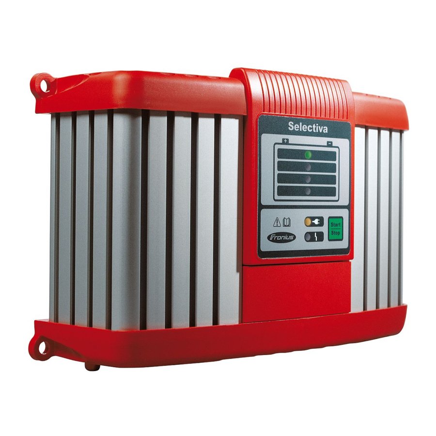
Control panel
The control panel (LED version) is explained below.

- State of charge indicator 25%
- State of charge indicator 50%
- State of charge indicator 75%
- State of charge indicator 100%
- Ready indicator
- -
- Start/Stop and setup button
- for interrupting and restarting charging.
- for selecting the characteristic type (press and hold for 10 s).
- Error indicator
Plugging in options
NOTE:
Danger from connecting options and accessories while the mains plug is plugged in.
This can result in damage to the device and accessories.
- Only connect options and system add-ons when the mains plug is unplugged and the charging leads are disconnected from the battery.
Connections

Bottom of housing
| No. | Function |
| (1) | AC input - mains socket |
| (2) | Mains cable safety bow for fitting the mains cable. |
| (3) | Connection P2 - I/O port for options on the I/O port. |
| (4) | Connection P1 - charger lead socket also for external stop and temperature-controlled charging options. |

Top of housing
| No. | Function |
| (5) | Removable display |
| (6) | Connection P3 - Visual Port for connecting the internal display. |
| (7) | Connection P4 - Multi Port for connecting the following options:
|
Removing covers for connections and options

If necessary, use a screwdriver to remove:
- Cover (1) for connection P4 - Multi Port.
- Cover (2) for connection P2 - I/O port.
Leave covers (1) and (2) in place on unused P2 and P4 connections.
USB update option
The USB update option allows the charger to be updated directly via the USB interface.
Fitting the optional bracket and strain-relief device for the charging lead

Please note:
the torque for all screws is 2.5 Nm (1.84 ft. lb.).
To fit the bracket:
- Undo the screws (1).
- Fit bracket (2) using the previously removed screws.
To fit the strain-relief device:
- Undo screw (3).
- Fit charging lead strain-relief device (4) using the previously undone screw.
Edge guard option

The edge guard removal process is the reverse of the fitting process.
The bracket cannot be fitted if the edge guard is already in place.
Wall bracket option
Different wall plugs and screws will be required depending on the supporting surface. Wall plugs and screws are therefore not included in the scope of supply. The installer is responsible for selecting the right wall plugs and screws.

Preparations for security lock

The security lock is not contained in the scope of supply.
A security lock can only be attached
- to the groove on the housing as shown.
- to the groove on the housing that is exactly opposite.
- using spacer M8 DIN 125 or DIN 134, located as shown.
Installation
If installing the charger on a firm base, use the drilling template enclosed in the packaging.
If the charger is installed in a switch cabinet (or a similar sealed area), then forced-air ventilation must be provided to ensure adequate heat dissipation. There must be a clearance of 10 cm (3.94 in.) all around the charger.
The space requirement measurements in mm (inches) illustrated below are given to ensure that there is easy access to the plug connections:

Charging the battery
Starting charging

Risk of damage if attempting to charge a faulty battery or using the incorrect charging voltage.
This can result in damage to property.
- Before beginning charging, ensure that the battery to be charged is fully functional and the charging voltage of the device matches the battery voltage.
- Connect the mains cable to the charger and plug into the mains.
- Charger is on standby. Ready indicator lit.
- Select characteristic type according to the battery to be charged.
Please note:
Information on which characteristic type to select can be found in the "Setup menu" section or the enclosed characteristic data sheet.
Danger due to incorrectly connected charging plugs.
This may result in serious injury and damage to property.
- Connect charging leads to the correct poles and ensure proper electrical connection to the battery poles.
- If using the vehicle power supply, switch off the ignition and all other devices consuming power.
- Connect the charging lead (red) to the positive pole (+) on the battery.
- Connect the charging lead (black) to the negative pole (-) on the battery.
- Charging begins automatically after approx. 2 seconds.
- A set of four LEDs shows the battery's state of charge.

- Conservation charging: once the battery is fully charged, the charger automatically switches to conservation charging to prevent self discharge of the battery. The battery can remain connected to the charger for any length of time.
![]()


Finishing charging
Danger due to ignition of oxyhydrogen caused by sparks generated when the charging plug is disconnected prematurely.
This can result in serious injury and damage to property.
- Before disconnecting the charging plug, press the Stop/Start button to finish charging.
- Press the Stop/Start button to complete charging.
- Disconnect the charging lead (black) from the negative pole (-) on the battery.
- Disconnect the charging lead (red) from the positive pole (+) on the battery.
When the charging contacts are open, the automatic open circuit voltage detection ensures that the charging contacts are de-energised.
Interrupting charging
NOTE!
Danger from disconnecting or unplugging the charging lead during charging.
This can result in damage to the connection sockets and connecting plug.
- Do not disconnect or unplug the charging lead while charging.
- Press the Stop/Start button while charging.
- The process is interrupted.
- Ready indicator flashes.
- Press the Stop/Start button again to continue charging.
Setup menu
General remarks
Select the characteristic type in the Setup menu depending on either the battery to be charged or the requirement as specified in the accompanying characteristic data sheet.
Accessing the Setup men
Please note:
Do not connect the charging lead to the battery.
A characteristic type cannot be selected when the charging plug is connected.
- Connect the mains cable to the charger and plug into the mains.
- Charger is on standby - ready indicator is lit.
- Press and hold the Start/Stop button for approx. 10 seconds to call up the Setup menu.
- Ready indicator goes out. The charger is in Setup mode. The display also shows the selected characteristic type.
![]()

Selecting the characteristic type
- Press the Start/Stop button to select the characteristic type according to the enclosed characteristic data sheet.
- If there is no further selection within 10 seconds, the selected characteristic type is saved.
![warning]() Please note:
Please note:
Do not connect a battery during these 10 seconds.
Continue as described in the section "Charging the battery".
![]()
- Ready indicator lights up. Once the new characteristic type has been selected, the charger is automatically ready for the next charging sequence.

Troubleshooting
Safety

Risk of electric shock.
This can result in serious injuries or death.
Before opening the device:
- Unplug the device from the mains.
- Disconnect battery.
- Put up an easy-to-understand warning sign to stop anybody inadvertently switching it back on again.
- Using a suitable measuring instrument, ensure that electrically charged components (e.g. capacitors) have been discharged.
Danger from an inadequate ground conductor connection.
This can result in severe personal injury or damage to property.
- The housing screws provide a suitable PE conductor connection for earthing the housing and must NOT be replaced by any other screws that do not provide a reliable PE conductor connection.
Protection devices
- Ready indicator flashing, error indicator flashing:
![]()
Cause: Mains fault - mains voltage outside the tolerance range.
Remedy: Check mains conditions. - Ready indicator lit, error indicator flashing:
![]()
- Cause: Short circuit on the charging plug or charger lead. Short circuit detection active.
Remedy: Check charger leads, contacts and battery poles. - Cause: Battery overvoltage or undervoltage.
Remedy: Select correct charging characteristic/function, or set correct battery voltage.
- Cause: Short circuit on the charging plug or charger lead. Short circuit detection active.
- Ready indicator lit, error indicator lit:
![]()
Cause: Polarity reversal of charger leads. Reverse polarity protection has tripped.
Remedy: Connect battery poles correctly. - Charger switches off during charging:
Cause: Ambient temperature too high. Overtemperature protection active.
Remedy: Allow device to cool down. Charging will recommence automatically once the device has cooled sufficiently. If not, have it checked by a workshop.


Charging errors
Ready indicator lit, error indicator flashing, SOC indicator 1/2/3/4 flashing:

Cause: Timeout in the corresponding charging phase or battery capacity too high.
Remedy: Select correct characteristic type according to the enclosed characteristic data sheet and charge again.
Cause: Battery faulty (cell short circuit, heavy sulphation).
Remedy: Check battery and replace if necessary.
Cause: Optional external temperature sensor has tripped due to over or undertemperature.
Remedy: Allow battery to cool, or charge battery in a more suitable area.
Technical data
Selectiva 1 kW
| Mains voltage (+/- 15%) | ~230 V |
| Mains frequency | 50/60 Hz |
| Mains fuse | 16 A |
| Battery backfeed current | < 1 mA |
| Standby consumption | max. 1.7 W |
| Safety class | I |
| Max. permitted grid impedance Zmax on PCC | None |
| EMC emission class | A |
| Dimensions L x W x H | 247 x 162 x 88 mm (9.72 x 6.38 x 3.46 in) |
| Weight (without cables) | |
| 1020 | 1030 | 2010 | 2015 2020 | 2032 | 2040 | 2.1 kg (4.63 lb.) 2.2 kg (4.85 lb.) |
| Cooling | |
| 1020 | 1030 | 2010 | 2015 2020 | 2032 | 2040 | Convection Convection and fan |
| Operating temperature (>30°C / >86°F derating) | -20°C to +40°C (-4°F to 104°F) |
| Storage temperature | -40°C to +85°C (-40°F to 185°F) |
| Relative humidity | maximum 85% |
| Maximum altitude above sea level | 2000 m (6561 ft.) |
| Protection class | IP 40 |
| Mark of conformity | According to rating plate |
| Housing | A1 |
| Product standard | IEC 60068-2-27 (shock) IEC 60068-2-29 (bump) IEC 60068-2-64 (vibration) EN 60335-1 EN 60335-2-29 EN 61000-3-2 EN 61000-6-2 (EN 61000-4-2, EN 61000-4-3, EN 61000-4-4, EN 61000-4-5, EN 61000-4-6, EN 61000-4-11) EN 61000-6-4 (Class A) |
Device-specific data
| Device | Grid current max. | Effective power max. | Nominal output voltage | Output voltage range | Output current |
| 1020 | 2.3 A | 315 W | 12 V DC / 6 cells | 2 V to 16.8 V DC | 20 A at 14.4 V DC |
| 1030 | 2.9 A | 420 W | 12 V DC / 6 cells | 2 V to 16.8 V DC | 30 A at 13.5 V DC |
| 2010 | 2.3 A | 340 W | 24 V DC / 12 cells | 2 V to 33.6 V DC | 10 A at 28.8 V DC |
| 2015 | 2.7 A | 410 W | 24 V DC /12 cells | 2 V to 33.6 V DC | 15 A at 24 V DC |
| 2020 | 4 A | 650 W | 24 V DC /12 cells | 2 V to 33.6 V DC | 20 A at 28.8 V DC |
| 2032 | 7.6 A | 1030 W | 24 V DC /12 cells | 2 V to 33.6 V DC | 32 A at 28.8 V DC |
| 2040 | 7.7 A | 1120 W | 24 V DC /12 cells | 2 V to 33.6 V DC | 35 A at 28.8 V DC |
SPARE PARTS ONLINE

contact@fronius.com
www.fronius.com
At www.fronius.com/contact you will find the contact details of all Fronius subsidiaries and Sales & Service Partners.
Documents / Resources
References
Download manual
Here you can download full pdf version of manual, it may contain additional safety instructions, warranty information, FCC rules, etc.
Advertisement


Need help?
Do you have a question about the Selectiva and is the answer not in the manual?
Questions and answers