
Related Manuals for Fronius Selectiva 3.0


Summary of Contents for Fronius Selectiva 3.0
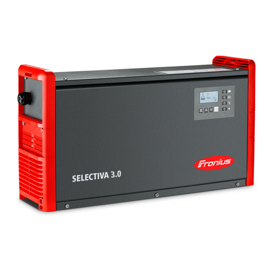
- Page 1 Operating Instructions Selectiva 3.0 2-3 kW Operating Instructions 42,0426,0361,EN 012-12042023...
-
Page 3: Table Of Contents
Contents Power categories General 2 kW 3 kW Safety rules General Environmental conditions Mains connection Dangers due to grid and charging current Danger due to acid, gases and vapours General information on working with batteries Personal protection and protection of others Safety measures in normal operation EMC device classifications EMC measures... - Page 4 Additional functions General settings Reset settings USB mode Status codes Options Safety Electrolyte circulation 3 kW External start/stop Temperature-controlled charging LED strip Air filter Wall and floor bracket "Mobile" kit Option box Remote control system Mounting plate TagID TagID Link Technical data Selectiva 2 kW Selectiva 3 kW...
-
Page 5: Power Categories
Power categories General The kW information for the power categories relates to the housing design and is not directly related to the actual device output. 2 kW Selectiva 2040/2050/2060/2070 4020/4035 3 kW Selectiva 2080/2100/2120 4045/4060... -
Page 6: Safety Rules
Safety rules General The device has been manufactured in line with the state of the art and according to recognized safety standards. If used incorrectly or misused, however, it can cause: Serious or fatal injury to the operator or third parties Damage to the device and other material assets belonging to the operating company Inefficient operation of the device... -
Page 7: Dangers Due To Grid And Charging Current
IMPORTANT! Ensure that the grid connection is earthed properly! Dangers due to Working with battery chargers poses a number of dangers, such as: grid and char- Electrical hazard due to grid and charging current ging current Hazardous electromagnetic fields that may pose a risk of death for individu- als with pacemakers. -
Page 8: Personal Protection And Protection Of Others
Personal protec- Keep persons, especially children, away from the device and working area during tion and protec- operation. However, if persons are in the vicinity: tion of others Inform them of any dangers (hazardous acids and gases, risk due to grid and charging current, etc.), Provide suitable protective equipment. -
Page 9: Maintenance
Maintenance Before each start-up, check the mains plug and mains cable and charging cables and charging terminals for damage. If dirt accumulates on the device, clean the surface of the device housing with a soft cloth and only with solvent-free cleaning agents. Maintenance and Maintenance and repair work must only be carried out by authorised personnel. -
Page 10: Copyright
Copyright Copyright of these Operating Instructions remains with the manufacturer. Text and illustrations were accurate at the time of printing. Fronius reserves the right to make changes. The contents of the Operating Instructions shall not provide the basis for any claims whatsoever on the part of the purchaser. If you... -
Page 11: General Information
General information Explanation of DANGER! safety notices Indicates immediate danger. ▶ If not avoided, death or serious injury will result. WARNING! Indicates a potentially hazardous situation. ▶ If not avoided, death or serious injury may result. CAUTION! Indicates a situation where damage or injury could occur. ▶... -
Page 12: Grid Connection
WARNING! Danger from charging unsuitable batteries. Serious personal injury and property damage as a result of escaping gases, igni- tion, or explosion may result. ▶ Only connect batteries to the battery charger which are suitable for the bat- tery charger in terms of their type, voltage, and capacity and which corres- pond to the settings on the battery charger. -
Page 13: Charging Lead
Charging lead WARNING! Danger from flying sparks due to improper disconnection of the charging plug. This can result in severe personal injury and damage to property. The resulting sparks can ignite the charging gases that form during charging and cause a fire or explosion ▶... -
Page 14: Warning Notices On The Device
AC max. DC nom. DC max. IP21 Protective class I Fronius International GmbH Froniusstraße 1 4643 Pettenbach Austria Do not dispose of used devices with domestic waste. Dispose of them according to the safety rules. Possible sources of ignition, such as fire, sparks and naked flames, must be kept away from the battery. -
Page 15: Warning Notices Inside The Device
Warning notices WARNING! inside the device Danger from electric shocks. This can result in serious injury or death. ▶ The housing must never be opened by anyone other than a service technician trained by the manufacturer. ▶ The device must be disconnected from the mains before starting any work with the housing open. - Page 16 The device can be set up and operated in dry, closed rooms in accordance with protection class 21. Avoid exposure to moisture. The permissible operating position of the device is horizontal. Cooling air The device must be set up so that cooling air can flow through the housing open- ings provided unhindered.
-
Page 17: Wall And Floor Bracket
Wall and floor WARNING! bracket Danger from incorrectly performed work and falling equipment. This can result in severe personal injury and damage to property. ▶ The mounting must only be carried out by trained and qualified personnel. Depending on the substrate, different dowels and screws are required. Therefore, dowels and screws are not part of the scope of supply. - Page 18 341 (13.43) 110 (4.33) 38 (1.5) 123,5 (4.86) 91,5 (3.6) 182 (7.17) 220 (8.66) 123 (4.84) 11 (.43) 266 (10.47) 2 kW (B1) mm (in.) 8.5 (.33)
- Page 19 110 (4.33) 417 (16.42) 38 (1.5) 123,5 (4.86) 182 (7.17) 123 (4.84) 38 (1.5) 220 (8.66) 40 (1.57) 89,5 (3.52) 11 (.43) 342 (13.46) 3 kW (C1) mm (in.) 8,5 (.33)
-
Page 20: Control Elements And Connections
Control elements and connections Operating con- trols and con- nections Function USB port The USB port allows a USB flash drive to be used to update the device and also to log the charging parameters while charging is in progress. Position for options - External start/stop option - Temperature-controlled charging option... -
Page 21: Pin Assignment Of The 2 Kw Option Plug
Function Control panel LED strip option Lights up in the appropriate col- ors depending on the state of charge, according to the indic- ators explained in the "Control panel" section Cover for option plug and char- ging cables The option plug and the char- ging cables are only accessible by removing the cover (9). -
Page 22: Pin Assignment Of The 3 Kw Option Plug
Plug Plug Code Function Code Function Dete Detect wire white C2 G CAN 2 GND wire brown C1 G Remote Control wire 4 13 V 13 V Remote Control Power Option Box wire brown wire 1 CBG Easy GND Supply Option Box wire white CBG Easy VCC... - Page 23 Plug Plug Code Function Code Function Status 1 Dete Detect wire white Status 2 C2 G CAN 2 GND wire brown C1 G Remote Control wire 4 13 V 13 V Remote Con- trol wire 1 Option Box wire brown Power Option Box Supply...
-
Page 24: Control Panel
Control panel Function Display "Menu" key Selects the desired menu. Return to the higher-level menu. "Up/Down" keys Selects the desired menu item. Sets the desired value. “Pause/Start” key For interrupting and resuming the charging process. Confirms a menu item or setting. "Battery cooled"... - Page 25 "Charge" indicator (yellow) Lit: during charging. Flashes: if charging has been interrupted. "Battery is charged" indicator (green) Lights up continuously: Charge complete. Flashes every second: Charge complete. The water refill indicator has also been activated. Detailed information can be found in the Additional func- tions section of the "Display"...
-
Page 26: Charging The Battery
Charging the battery Starting for the When the battery charger is connected to the grid for the first time, the device is first time in SETUP mode. In this mode, the following basic settings must be made or confirmed: Language (English, German, French, etc.) Date, time, and time zone Units: metric / imperial Charging cable length and charging cable cross-section... -
Page 27: Starting The Charging Process
Use the "Up/Down" buttons to set the appropriate charging cable length (m / ft). Confirm with the "Pause/Start" button. The battery charger is configured with the correct charging cable length ac- cording to the order. An incorrectly set charging cable length can have a negative effect on the charging process! Use the "Up/Down"... - Page 28 WARNING! Danger due to incorrect type of battery and incorrect charging settings. This can result in severe personal injury and damage to property. ▶ Before starting the charging process, make sure that the correct type of bat- tery is set on the battery charger. ▶...
-
Page 29: Interrupting The Charging Process
The battery symbol indicates the current state of charge. The more bars are dis- played, the further the charging process has progressed. As soon as the battery is fully charged, a minute counter appears (figure on the right). This counts the minutes since the end of charging and makes it easier to judge which battery has cooled down the most when using several battery chargers. -
Page 30: Stopping Charging
As long as a battery is connected to the charger, only the charging process can be interrupted and resumed using the "Pause/Start" key. Display modes can be changed using the "Menu" key as described in the "Display" section, but this is only possible when no battery is connected to the charger. - Page 31 Disconnect the charging plug. When the charging contacts are open, the automatic open circuit voltage detec- tion ensures that the charging contacts are de-energised.
-
Page 32: Display
Display Overview of dis- Function play modes Standard mode In standard mode the display shows the charging parameters. Statistics mode Visualises the frequency of the device operating modes and shows the total number of charging actions. Also shows an overview of the total and average Ah produced and energy consumed per charge. -
Page 33: Menu Selection
Menu selection Change from standard mode to the menu selection as follows: Press and hold the "Menu" key for approx. 5 seconds. Change from all other modes to the menu selection as follows: Briefly press the "Menu" key. To select the desired mode: Use the "Up/Down"... - Page 34 Use the "Up/Down" keys to switch between the pages for each stored char- ging process. Contents of the display window Charge start date, e.g.: Thursday, 19/06/14. Charge start time, e.g.: 19:29 or charging time, e.g.: 8 h 28 min. Voltage at charge start, e.g.: 45.9 V. Voltage after 5 minutes, e.g.: 47.9 V.
- Page 35 Key symbol with a cross Charging was stopped without using the "Pause/Start" key. Charging details Displays certain battery data at the beginning and end of the charging process: Number of cells Characteristic Type of battery Configuration Configuration mode provides the following setting options: mode "Charging settings": settings for the battery Type of battery, e.g.
-
Page 36: Configuration Mode
“Reset Settings” Includes a double-check prompt ("OK?") that requires the operator to recon- firm that this step is intended. First the screen will appear in its initial format, showing the date, time and software version. The "Up/Down" keys can be used to retrieve the following information: Serial number of the charger plus serial number and version of the con- figuration memory. - Page 37 When you select a menu item you may be presented with a prompt to read the Operating Instructions. Confirm this prompt by pressing the "Pause/ Start" key again. The procedure for navigating the configuration menu and its submenus is as fol- lows: Use the "Up/Down"...
-
Page 38: Overview Of Charging Settings
Use the "Up/Down" keys to select the desired parameter (e.g. "Cells"). Use the "Pause/Start" key to confirm the parameter. Use the "Up/Down" keys to set the desired value (e.g. "24" for the number of battery cells). Use the "Pause/Start" key to confirm what you have entered. If one or more relevant settings are changed for the charging process in configur- ation mode, you will once again be prompted to confirm acceptance of the changed settings when exiting configuration mode. -
Page 39: Electrolyte Circulation
Electrolyte cir- "Air Pump" electrolyte circulation (not culation available on the Selectiva 220 V vari- ant): The electrolyte circulation cycle is controlled by the charger's control system. A number of selection options are available for this purpose. The following settings are available for electrolyte circulation: Electrolyte circulation switched off. -
Page 40: Equalising Charge
The following settings are available for temperature-controlled charging: automatic/OFF/required automatic ... Temperature-dependent adjustment of the charging character- istic. OFF ... The measured battery temperature is not taken into account. required ... Charging only starts if the temperature sensor is connected. Error overtemperature ON/OFF ON ... -
Page 41: Delay
Delay If the battery remains connected to the charger for the duration of the equalising charge delay ("equalize charge delay"), a special type of charging takes place. This prevents acid stratification. The parameters for the current (ampere/100 ampere hours), voltage (volt/ cell) and duration of the equalising charge may all be changed. -
Page 42: Calendar
If the "Automatic/continue charging" option is activated, the charging process is automatically continued after a fault in the electrical network as soon as the electrical network is available again. Calendar Calendar The calendar function allows charging to be started automatically according to the following criteria: Time window in which charging may not be started if a battery is connected. - Page 43 NOTE! Ongoing charging operations are unaffected by the set time windows. ▶ If, in the example above, a battery is connected at 05:45, the charge end time is governed according to need and is not interrupted by the end time specified for the set time window (06:00 in the example).
-
Page 44: Special Charges
Special charges Special Charges Selecting "Special Charges" allows one or more of the alternative charging types to be performed temporarily. The "repeat" setting defines how often the alternative charging mode should be performed until the device reverts to the original charging parameters again: Setting range 1 to 99 repetitions Disable Start Button... -
Page 45: Dc Connection
When opportunity charging is "ON" and a battery is connected, the following ap- pears: Display when RI characteristic is selected Display for other characteristics (e.g. IUI) To start opportunity charging: Use the "Up" key to select the runner symbol (1). "Runner symbol"... - Page 46 A list appears with the following selection options: The individual selection options are explained in greater detail below: Setting the "Blue LED" indicator Time (minutes) that must be allowed to pass before the blue "battery cooled" in- dicator comes on to indicate that a battery has cooled down sufficiently. The time from the end of charging is used as the setting.
-
Page 47: General Settings
If set to "OFF", the refilling request does not have to be confirmed. Option Section Option Section 1 Setting options: CAN1 (option box) Cool Bat Guide Easy (Fronius variants only) Option Section 2 (3 kW only) Setting options: CAN2 (option box) AirPuls (EUW) - Page 48 Select the "general options" menu item. A list appears with the following selection options: Language Display settings Contrast LED brightness Show Ah at charge end ON/OFF Time and Date daylight saving time / normal time Predefined time zones User-defined time zones Charging cable: Basic length of charging cable (m) Cable cross section:...
-
Page 49: Reset Settings
Temperature: Temperature in °C / °F Code: Code entry required / not required to access configuration mode ("Code ON / OFF") USB Logging Time: Time interval (s) for recording charging parameters on the USB flash drive (USB Logging Time) Reset statistics Reset history For more detailed information on the statistics and history, please refer to the "Statistics mode"... - Page 50 I-SPoT-VIEWER software (www.fronius.com/i-spot) supports the visualiza- tion and evaluation of the data on the USB thumb drive. To start a data download, confirm this again with the "Pause/Start" button. If this repeated confirmation with the "Pause/Start" button is not carried out, the download starts automatically after one minute.
-
Page 51: Status Codes
If a USB thumb drive is plugged in during charging, the csv files are saved directly on the USB thumb drive. The folder structure, which is also cre- ated automatically, contains the "Datalog" folder instead of the "Charges" folder. Status codes If a fault occurs during operation, specific status codes may be displayed. - Page 52 Status codes in the event of a battery fault Cause/Remedy (22) Battery undervoltage (23) Battery overvoltage (24) Battery too hot (only with external temperature sensor) (25) Battery undertemperature (only with external temperature sensor) (26) Cell defect detected (27) Battery not supported (28) Battery heavily discharged - safety charge in progress (29)
- Page 53 Status codes in the event of a gateway error Cause/Remedy (101) CAN Connect setting is active and no CAN connection could be estab- lished to the gateway for at least 2 minutes. (102) Gateway has no connection to the back-end. Status codes in the event of a TagID error Cause/Remedy (200) Set technology on the battery charger is not compatible with the connec-...
- Page 54 (505) Over-/undervoltage in intermediate circuit (506) Asymmetry in intermediate circuit (507) Primary supply voltage out of tolerance (508) Grid failure (509) Incorrect device configuration (510) Primary EEPROM faulty (527) Phaseshifter overcurrent (528) High charge relay switched off during load operation (530) Communication problem (532) Microcontroller error (e.g., division by 0) (533) Reference voltage out of tolerance...
- Page 55 Status codes in the event of an error in the control system Cause/Remedy (540) Configuration memory block missing/defective (541) No secondary communication (542) Secondary Init failed (543) Program/memory error in the curve control (544) Program/memory error in the curve control (545) Primary Init failed (546) Update failed (547) Load/save settings failed...
-
Page 56: Options
Options Safety The housing has to be partially opened to connect the options. WARNING! Danger of electric shock. This may result in serious injuries or death. ▶ The housing must never be opened by anyone other than a service technician trained by the manufacturer. - Page 57 mixing of the electrolyte to take place. The benefit is the reduced heating of the battery, and consequently longer battery-life, plus reduced water loss during charging. If a pump fault or leaks in the connection with the battery result in a fault being detected, then the status code "Statecode 14"...
-
Page 58: External Start/Stop
mm (in.) 464 (18.27) 110 (4.33) External start/ The external start/stop option prevents spark formation at the charging plug if it stop is disconnected during charging. Special contacts inside the charging plug re- gister a disconnection. These contacts are leading in comparison to the main contacts. -
Page 59: Air Filter
Air filter In dusty environments, the air filter prevents the inside of the device from be- coming dirty. This avoids a possible reduction in power and other problems. De- tailed information can be found in the corresponding User Information. Cleaning interval as required (manufacturer's recommendation: monthly) Wall and floor The robust wall and floor bracket with integrated cable holder ensures safe in- bracket... -
Page 60: Tagid Link
mm (in.) 482 (18.98) 115 (4.53) 425 (16.73) 428 (16.85) 456 (17.95) 462 (18.19) 415 (16.34) 418 (16.46) 446 (17.56) 3 kW (C1) 452 (17.80) TagID The TagID is an electronic measurement and control system that exchanges bat- tery data with the battery charger and optimizes charging. TagID Link The TagID Link enables the exchange of relevant battery data between the TagID and the battery charger. -
Page 61: Technical Data
Technical data Selectiva 2 kW ~ 230 V, ± 15% Mains voltage Grid frequency 50/60 Hz max. 16 A Mains fuse protection Minimum mains lead cross section 1.5 mm² (0.002325 in.²) Protection class I (with ground conductor) Max. permitted mains impedance Z None Standby usage 4.9 W... -
Page 62: Selectiva 3 Kw
Max. Device-specific Max. AC Max. AC Nominal charging data current power voltage current Weight 2070 2 kW 12.1 A 2350 W 24 V 70 A 6.1 kg (13.45 lb) 4020 2 kW 7.9 A 1530 W 48 V 20 A 5.8 kg (12.79 lb) 4035 2 kW... - Page 63 A high ambient temperature may result in power degradation (derating). Max. Device-specific Max. AC Max. AC Nominal charging data current power voltage current Weight 2080 3 kW 15.1 A 3040 W 24 V 80 A 8.2 kg (18.08 lb) 2100 3 kW 15.3 A 3290 W 24 V...
Need help?
Do you have a question about the Selectiva 3.0 and is the answer not in the manual?
Questions and answers