Stabila TECH 196 / 196 M / 196 Dark Shadow Manual
- User manual (22 pages) ,
- User manual (22 pages) ,
- Manual (2 pages)
Advertisement
Intended use
The STABILA TECH 196 / 196 M is a digital measuring tool for measuring inclinations. If you still have questions after reading through the operating instructions, you can obtain advice by telephone: +49 63 46 3 09 0 1.800.869.7460 U.S. and Canada
Equipment and functions:
- Vertical vial(s) for vertical levelling, in reverse position too
- Horizontal vial for horizontal levelling, in reverse position too
- Electronic module with 2 digital displays for accurately determining inclinations and angles
- TECH 196 M: Extra-strong rare-earth magnets
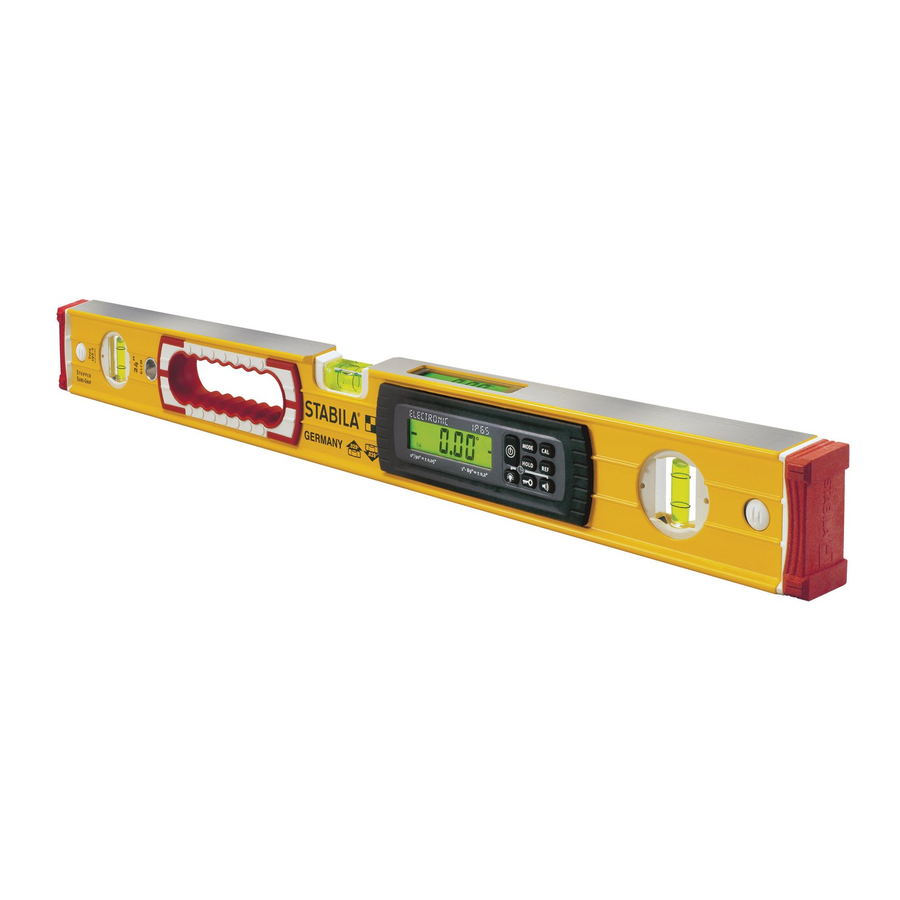
Components of the unit

- Electronic module (dust-proof and waterproof in accordance with IP 65)
- Battery compartment lid
- 2 Displays
- Vials - vertical and horizontal
- Removable, shock-absorbing end caps
- Anti-slip stopper
- Rare-earth magnet ( 196 M )
Buttons:
 | (8) | On/Off |
 | (9) | Units of measurement: °, %, mm/m, in/ft |
 | (10) | Calibration and sensor adjustment |
 | (11) | HOLD – locking measurements |
 | (12) | Reference – freely selectable zero position |
 | (13) | Acoustic guidance |
 | (14) | Key lock |
 | (15) | Display lighting |
Display elements

- Elements for visual guidance
- Acoustic guidance: activated
- Battery low – see "Inserting batteries/battery replacement" chapter
- Units of measurement: °, %, mm/m, in/ft
- Significant temperature change
- Reference: activated
- Sensor calibration necessary
- Key lock: activated
Commissioning
Inserting batteries/battery replacement
Unscrew battery compartment lid on rear, insert new batteries according to symbol in battery compartment. Suitable rechargeable batteries can also be used.
LCD: low battery charge - insert new battery

 Dispose of used batteries at suitable collection points - not with household waste. Do not leave in unit!
Remove the batteries if you do not intend to use the unit for some time!
Switching the unit on
After switching on with the "ON/OFF" button, an automatic test is carried out. All the display's segments are shown.
After the end of the test, the version number S x.xx of the software is briefly displayed and the automatic switch-off time (Auto OFF) is shown.
An acoustic signal indicates that the unit is ready for operation. The display shows the angle measured in the set unit of measurement.

Functions
Visual guidance
In the range of ± 15° to the horizontal (0°) or to the vertical (90°), arrows show which way to turn the digital protractor to reach 0° or 90°.
The 2 "centre display" bars indicate the precise position at which 0° or 90° is reached.

Acoustic guidance
The acoustic guidance is activated/deactivated using the "Loudspeaker" button. The tone sequence speeds up as the 0° or 90° position is approached in a range of ± 2°. A change in the pitch indicates that these positions have been exceeded.
A continuous tone confirms the precise point at which 0° or 90° is reached.

Automatic display inversion
The display is inverted for overhead measurements so that they are always easy to read.

Setting the MODE unit of measurement
The unit of measurement is set by pressing the "MODE" button several times.

 | °Fine: | Display in 0.01° steps |
| ° Rough: | Display in 0.1° steps |
| %: | Display in 0.1% steps |
| mm/m: | Display in 1 mm/m steps |
| in/ft decimal: | Display in 0.01 in/ft steps |
| in/ft fraction: | Display in 1/8 in/ft steps |
The set unit of measurement is retained after the unit is switched off.
Locking the measurement with HOLD
The current measurement can be locked by pressing the "HOLD" button. The visual guidance indicator flashes. The measurement is displayed continuously. The locked measurement is deleted by pressing the "HOLD" button again or switching the unit off.

Freely selectable zero position REF
The "REF" button can be used to select any set angle as 0° reference. The angle details now displayed relate to this reference angle. The displayed value flashes with this setting.

- The reference angle value is displayed for 2 seconds by briefly pressing the "REF" button.
- The reference angle is deleted by:
- pressing and holding (≥ 3 sec) the "REF" button. The activated button lock must be released before deleting the angle.
- Switching off
- The automatic switch-off function
The zero position then refers back to the original setting.
The alignment selected for the digital protractor must not be changed during the reference function, as this could lead to a display error.

Lighting
Briefly pressing the "Lighting" button switches the display lighting on for approx. 60 seconds.
Pressing and holding (≥ 5 sec) the "Lighting" button makes the lighting darker and switches it on permanently.
The lighting is switched off by pressing the "Lighting" button again, or by switching off the unit.

Key lock
Function: Key lock to prevent inadvertent activation. Display after activation: key symbol.
The lock is activated for the following buttons: "MODE, CAL, HOLD, REF"
The key lock remains active after switching the unit off and back on again! Pressing and holding (≥ 3 sec) the "Key" button disables the key lock.

Automatic switch-off time: Auto OFF
Pressing the "Lighting" and "Acoustic guidance" buttons at the same time allows the automatic switch-off time to be changed from 1/8 of an hour (approx. 7.5 minutes) to 2 hours. The set switch-off time is retained after the unit is switched off and is displayed briefly when it is switched on again.

Tilt function
The measuring surfaces of the electronic spirit level should be positioned precisely for all measurement work. If positioned at too great an angle, the tilt function prevents incorrect measurements. The display doesn't then show any measurements.

Checking the measuring tool
Accuracy check
To prevent incorrect measurements, the accuracy must be checked at regular intervals, e.g. before you start work, or after hard knocks or major changes in temperature.

- Switch on the electronic spirit level. Use the vial to accurately align the unit to a wall, for example, until the vial bubble is in the middle between the vial rings.
- Wait 10 seconds. If the value displayed is > 0.05°, the electronic spirit level must be recalibrated.
If mainly used for vertical measurements, the accuracy check can also be undertaken with the vertical vial.
Calibration

- Switch on the electronic spirit level. Use the vial to accurately align the unit to a wall, for example, until the vial bubble is in the middle between the vial rings. If mainly used for vertical measurements, the calibration can also be undertaken with the vertical vial.
- Hold the electronic spirit level in this position and press the CAL button. The CAL display shows calibration mode.
- Calibration starts when the CAL button is pressed again.
Newly calibrated value with deviation of ≥ 1° from factory setting  Recalibrate spirit level
Vibration during calibration Recalibrate spirit level
Calibration completed successfully Spirit level ready
The reverse test checks the calibration.
Angle ≤ 0.1° to normal position Spirit level ready
Adjusting the sensor
Calibration in 4 positions is needed if the following is displayed:

- The reverse test angle is ≥ 0.1° to the normal position --> too great a deviation.
- Change in internal reference
- Change in temperature since last calibration.
The electronic spirit level is calibrated in 4 measuring positions consecutively, turning 90° / 180° each time.
- All 4 planes are adjusted during the sensor adjustment.

- The sensor can only be adjusted if the two black bars appear on the display (in the range of 0° and 90°).
![]()
- CAL and the planes still to be adjusted flash alternately while the sensor is being adjusted for the respective plane..
![]()
- Planes that have not been adjusted flash in the display. Successfully adjusted planes are permanently indicated in the display.
![]()


Adjusting the sensor
- Simultaneously press the „MODE" and „CAL" buttons. Align the electronic spirit level accurately against a wall and press the CAL button to confirm.
![danger]() Step 1 must be performed with the vial. This ensures that the spirit level, the horizontal vial and the sensor are synchronised with each other.
Step 1 must be performed with the vial. This ensures that the spirit level, the horizontal vial and the sensor are synchronised with each other.
Align the electronic spirit level accurately against a wall and press the CAL button to confirm.
Flashing segments indicate the positions still to be calibrated.
Non-flashing segments indicate the positions already calibrated.


- The electronic spirit level is turned 180° and aligned using the arrows displayed.
The electronic spirit level is aligned horizontally using the arrows displayed.
The 2 „centre display" bars indicate the precise position at which the horizontal is reached.
Confirm with the CAL button.
Flashing segments indicate the positions still to be calibrated.
Non-flashing segments indicate the positions already calibrated.

- The electronic spirit level is turned 90° and aligned vertically using the arrows displayed. The 2 „centre display" bars indicate the precise position at which the vertical is reached. Confirm with the CAL button. The flashing segment indicates the position still to be calibrated. Non-flashing segments indicate the positions already calibrated.

- The electronic spirit level is turned 180° and aligned vertically using the arrows displayed.
The 2 „centre display" bars indicate the precise position at which the vertical is reached. Confirm with the CAL button.
„rdy" display: Calibration in 4 positions successfully completed!


Error messages

Display: Cal. /temperature
The sensor must be adjusted if the temperature or Cal. symbols are indicated in the display.
Display: Err
The unit must not be moved or subjected to vibrations during the calibration/sensor adjustment. This can lead to measurement errors.
Display: - - - -
Unit inclination around longitudinal axis > 10°
Technical data
| Accuracy: Electronic module | |
| 0° / 90° / 180° / 270°: | ± 0,05° |
| In intermediate areas | ± 0,2° |
| Spirit level | |
| in normal position: | 0.5 mm / m = 0.029° |
| in reverse position: | 0.5 mm / m = 0.029° |
| Batteries: | 2 x 1.5 V alkaline, Mignon, AA, LR6, MN1500 |
| Operating life: | ≥ 150 hours |
| Operating temperature range: | -10°C to +50°C / 14°F to 122°F |
| Storage temperature range: | -20°C to +65°C / -4°F to 149°F |
| Protection class: | IP 65 |
Subject to technical modifications.
Safety information
Read the safety instructions and operating instructions through carefully.
Documents / ResourcesDownload manual
Here you can download full pdf version of manual, it may contain additional safety instructions, warranty information, FCC rules, etc.
Advertisement


Need help?
Do you have a question about the TECH 196 and is the answer not in the manual?
Questions and answers