Table of Contents
Advertisement
Advertisement
Table of Contents

Subscribe to Our Youtube Channel
Related Manuals for Stabila TECH 196


Summary of Contents for Stabila TECH 196
- Page 1 User manual...
-
Page 2: Table Of Contents
TECH 196 / 196 M Contents Section Page • 1. Intended use • 2. Safety information • 3. Components of the unit • 4. Display elements • 5. Commissioning • 5.1 Inserting batteries/battery replacement • 5.2 Switching the unit on •... -
Page 3: Intended Use
Congratulations on the purchase of your STABILA measuring tool. Read the safety instructions and operating instructions through carefully. The STABILA TECH 196 / 196 M is a digital measuring tool for measuring inclinations. If you still have questions after reading through... -
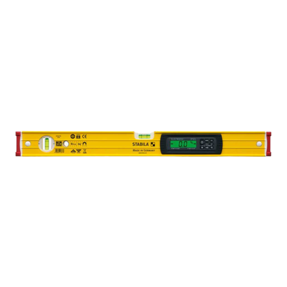
Page 4: Components Of The Unit
TECH 196 / 196 M 3. Components of the unit Electronic module (dust-proof and waterproof in accordance with IP 65) Battery compartment lid 2 Displays Vials - vertical and horizontal Removable, shock-absorbing end caps Anti-slip stopper Rare-earth magnet ( 196 M ) -
Page 5: Display Elements
TECH 196 / 196 M 4. Display elements Elements for visual guidance (16) (17) Acoustic guidance: activated Battery low – see chapter 5.1 (18) Units of measurement: °, %, mm/m, in/ft (19) Significant temperature change – see chapter 9 (20) -
Page 6: Commissioning
TECH 196 / 196 M 5. Commissioning 5.1 Inserting batteries/battery replacement Unscrew battery compartment lid on rear, insert new batteries according to symbol in battery compartment. Suitable rechargeable batteries can also be used. LCD: low battery charge - insert new battery... -
Page 7: Functions
TECH 196 / 196 M 6. Functions 6.1 Visual guidance In the range of ± 15° to the horizontal (0°) or to the vertical (90°), arrows show which way to turn the digital protractor to reach 0° or 90°. The 2 "centre display" bars indicate the precise position at which 0°... -
Page 8: Acoustic Guidance
TECH 196 / 196 M 6.2 Acoustic guidance The acoustic guidance is activated/deactivated using the "Loudspeaker" button. The tone sequence speeds up as the 0° or 90° position is approached in a range of ± 2°. A change in the pitch indicates that these positions have been exceeded. -
Page 9: Setting The Mode Unit Of Measurement
TECH 196 / 196 M 6.4 Setting the MODE unit of measurement 0,01° The unit of measurement is set by pressing the "MODE" button several times. 0,1˚ ° Fine: Display in 0.01° steps ° Rough: Display in 0.1° steps Display in 0.1 %... -
Page 10: Freely Selectable Zero Position Ref
TECH 196 / 196 M 6.6 Freely selectable zero position REF REFERENCE 20° The "REF” button can be used to select any set angle as 0° reference. The angle details now displayed relate to this reference angle. The displayed value flashes with this setting. -
Page 11: Lighting
TECH 196 / 196 M 6.7 Lighting Briefly pressing the "Lighting" button switches the display ≥ 5 sec lighting on for approx. 60 seconds. ∞ on = 60 sec on = Pressing and holding (≥ 5 sec) the "Lighting" button makes the lighting darker and switches it on permanently. -
Page 12: Tilt Function
TECH 196 / 196 M 7. Tilt function 5° 5° The measuring surfaces of the electronic spirit level should be positioned precisely for all measurement work. If positioned at too great an angle, the tilt function prevents 5° 5° incorrect measurements. The display doesn't then show... -
Page 13: Checking The Measuring Tool
TECH 196 / 196 M 8. Checking the measuring tool 8.1 Accuracy check To prevent incorrect measurements, the accuracy must be checked at regular intervals, e.g. before you start work, or after hard knocks or major changes in temperature. Step 1: Switch on the electronic spirit level. - Page 14 TECH 196 / 196 M Calibration 1. Switch on the electronic spirit level. Use the vial to accurately align the unit to a wall, for example, until the vial bubble is in the middle between the vial rings. If mainly used for vertical measurements, the calibration can also be undertaken with the vertical vial.
-
Page 15: Adjusting The Sensor
TECH 196 / 196 M 8.3 Adjusting the sensor Bei folgenden Anzeigen wird eine Sensorjustierung notwen- dig: 1. The reverse test angle is ≥ 0.1° to the normal position --> too great a deviation. 2. Change in internal reference 3. Change in temperature since last calibration. - Page 16 TECH 196 / 196 M 8.3 Adjusting the sensor Step 1: Simultaneously press the „MODE“ and „CAL“ buttons. Align the electronic spirit level accurately against a wall and press the CAL button to confirm. Step 1 must be performed with the vial. This ensures that the spirit level, the horizontal vial and the sensor are synchronised with each other.
- Page 17 TECH 196 / 196 M 8.3 Adjusting the sensor Step 2: The electronic spirit level is turned 180° and aligned using the arrows displayed. 180° The electronic spirit level is aligned horizontally using the arrows displayed. The 2 „centre display“ bars indicate the precise position at which the horizontal is reached.
- Page 18 TECH 196 / 196 M 8.3 Adjusting the sensor Step 3 The electronic spirit level is turned 90° and aligned vertically using the arrows displayed. The 2 „centre display“ bars indicate the precise position at which the vertical is reached. Confirm with the CAL button.
- Page 19 TECH 196 / 196 M 8.3 Adjusting the sensor Step 4 The electronic spirit level is turned 180° and aligned vertically using the arrows displayed. The 2 „centre display“ bars indicate the precise position at which the vertical is reached. Confirm with the CAL button.
-
Page 20: Error Messages
TECH 196 / 196 M 9. Error messages Display: Cal. /temperature The sensor must be adjusted if the temperature or Cal. symbols are indicated in the display. Display: Err The unit must not be moved or subjected to vibrations during the calibration/sensor adjustment. This can lead to measurement errors. -
Page 21: Technical Data
TECH 196 / 196 M 10. Technical data Accuracy: Electronic module 0° / 90° / 180° / 270° : ± 0,05° In intermediate areas ± 0,2° Spirit level in normal position: 0.5 mm / m = 0.029° in reverse position: 0.5 mm / m = 0.029°... - Page 22 Europe Middle and South America Australia Asia Canada Africa STABILA Messgeräte STABILA Inc. Gustav Ullrich GmbH P.O. Box 13 40 / D-76851 Annweiler 332 Industrial Drive Landauer Str. 45 / D-76855 Annweiler South Elgin, IL 60177 + 49 63 46 309 - 0 800-869-7460 info@stabila.de...
Need help?
Do you have a question about the TECH 196 and is the answer not in the manual?
Questions and answers