Table of Contents
Advertisement
Quick Links
Advertisement
Table of Contents

Subscribe to Our Youtube Channel
Related Manuals for Stabila TECH 500 DP


Summary of Contents for Stabila TECH 500 DP
- Page 1 TECH 500 DP How true pro’s measure User manual...
-
Page 2: Table Of Contents
TECH 500 DP Contents Section Page • 1 Intended use • 2 Safety information • 3. Components of the unit • 4. Display elements • 5. Commissioning • 5.1 Inserting batteries/battery replacement • 5.2 Switching the unit on • 6. -
Page 3: Intended Use
1. Intended use • Read the safety instructions and operating instructions Congratulations on the purchase of your STABILA measuring tool. The STABILA TECH 500 DP is a digital through carefully. measuring tool for measuring inclinations. • Keep these operating instructions in a safe place and... -
Page 4: Components Of The Unit
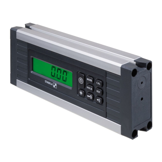
TECH 500 DP 3. Components of the unit TECH 500 DP (dust-proof and waterproof in accordance with IP 65) Battery compartment lid Display T-groove profile for securing with M4 groove stones, e.g. Bosch Rexroth or square nut in accordance with DIN 557 ®... -
Page 5: Display Elements
TECH 500 DP 4. Display elements Elements for visual guidance (15) Acoustic guidance: activated (16) See chapter 5.1 (17) (18) Units of measurement: °, %, mm/m, in/ft See chapter 7.4 (19) Reference: activated (20) See chapter 7.4 (21) Key lock: activated... -
Page 6: Commissioning
TECH 500 DP 5. Commissioning 5.1 Inserting batteries/battery replacement Unscrew battery compartment lid, insert new batteries into battery compartment according to symbol. Suitable rechargeable batteries can also be used. LCD indicator: Battery low – insert new batteries Alkaline Dispose of used batteries at suitable collection points –... -
Page 7: Functions
TECH 500 DP 6. Functions 6.1 Visual guidance In the range of ± 15° to the horizontal (0°) or to the vertical (90°), arrows show which way to turn the digital protractor to reach 0° or 90°. The 2 "centre display" bars indicate the precise position at which 0°... -
Page 8: Acoustic Guidance
TECH 500 DP 6.2 Acoustic guidance The acoustic guidance is activated/deactivated using the "Loudspeaker" button. The tone sequence speeds up as the 0° or 90° position is approached in a range of ± 2°. A change in the pitch indicates that these positions have been exceeded. -
Page 9: Setting The Mode Unit Of Measurement
TECH 500 DP 6.4 Setting the MODE unit of measurement MODE 0,01° The unit of measurement is set by pressing the "MODE" button several times. 0,1˚ ° Fine: Display in 0.01° steps ° Rough: Display in 0.1° steps Display in 0.1 %... -
Page 10: Freely Selectable Zero Position Ref
TECH 500 DP 6.6 Freely selectable zero position REF REFERENCE 20° The "REF" button can be used to select any set angle as 0° reference. The angle details now displayed relate to this reference angle. The displayed value flashes with this setting. -
Page 11: Lighting
TECH 500 DP 6.7 Lighting Briefly pressing the "Lighting" button switches the display > 5 sec lighting on for approx. 60 seconds. ∞ on = 60 sec on = Pressing and holding (≥ 5 sec) the "Lighting" button makes the lighting darker and switches it on permanently. -
Page 12: Checking The Measuring Tool
TECH 500 DP 7. Checking the measuring tool 7.1 Accuracy check To prevent incorrect measurements, the accuracy must be checked at regular intervals, e.g. before you start work, or after hard knocks or major changes in temperature. Step 1: Place the device with the lower measuring sole on as horizontal a surface as possible (e.g. -
Page 13: Calibration
TECH 500 DP 7.2 Calibration The measuring sole calibration is activated with the "CAL" button. -CAL- display: Step 1: Place the device with the lower measuring sole on as horizontal a surface as possible (e.g. table) with the display side facing the user. The first calibration is started by pressing the "CAL"... -
Page 14: Adjusting The Sensor
TECH 500 DP 7.3 Adjusting the sensor The sensor must be adjusted if the temperature or Cal. symbols are shown in the display. All 4 planes are adjusted during the sensor adjustment. The sensor can only be adjusted if the two black bars appear on the display (in the range of 0°... - Page 15 TECH 500 DP 7.3 Adjusting the sensor Step 1: Simultaneously press the "MODE" and "CAL" buttons. Step 2: Hold the unit in plane 1. Press the "CAL" button. If the plane has been adjusted successfully, it is permanently indicated in the display.
- Page 16 TECH 500 DP 7.3 Adjusting the sensor Step 3: Turn the unit by 90°to plane 2. Press the "CAL" button. If the plane has been adjusted successfully, it is permanently indicated in the display. Step 4: Turn the unit by 90°to plane 3.
-
Page 17: Error Messages
TECH 500 DP 7.3 Adjusting the sensor Step 5: Turn the unit by 90°to plane 4. Press the "CAL" button. If the last plane has been adjusted successfully, "rdy" is indicated in the display. 7.4 Error messages Display: Cal. /temperature The sensor must be adjusted if the temperature or Cal. -
Page 18: Technical Data
TECH 500 DP 8. Technical data Accuracy: 0° / 90° / 180° / 270° : ± 0,05° In intermediate areas ± 0,2° Batteries: 2 x 1,5 V alkaline, Mignon, AA, LR6, MN1500 Battery life: ≥ 150 hours Operating temperature range: -10 °C to +5o °C 14 °F to 122 °F... - Page 19 Europe Middle and South America Australia Asia Canada Africa STABILA Messgeräte STABILA Inc. Gustav Ullrich GmbH P.O. Box 13 40 / D-76851 Annweiler 332 Industrial Drive Landauer Str. 45 / D-76855 Annweiler South Elgin, IL 60177 + 49 63 46 309 - 0 800-869-7460 info@stabila.de...
Need help?
Do you have a question about the TECH 500 DP and is the answer not in the manual?
Questions and answers