Table of Contents
Advertisement
Quick Links
Advertisement
Table of Contents

Related Manuals for Stabila TECH 1000 DP


Summary of Contents for Stabila TECH 1000 DP
- Page 1 TECH 1000 DP How true pro's measure Operating instructions...
-
Page 2: Table Of Contents
• 7.5 Error messages Data transfer • 8. • 8.1 Querying the measurement • 8.2 Changing the bus address • 8.3 Error codes • 8.4 Auto mode • 8.5 Print mode • 9. STABILA Analytics evaluation software (optional) • 10. Technical data... -
Page 3: Intended Use
TECH 1000 DP 1. Intended use Congratulations on the purchase of your STABILA measuring tool. The STABILA TECH 1000 DP is a digital measuring tool for measuring inclinations. If you still have questions after reading through the operating instructions, you can obtain advice by... -
Page 4: Components Of The Unit
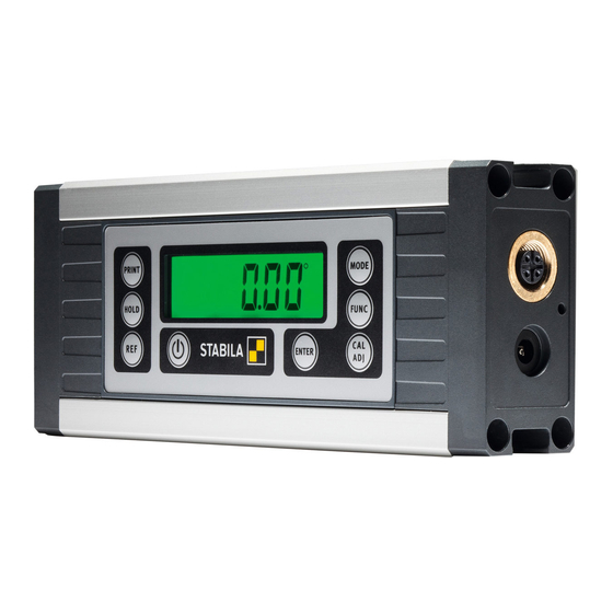
TECH 1000 DP 2. Components of the unit Display Mains adapter connection, M12 socket Rare-earth magnet T-groove profile for securing with M4 groove stones, e.g. Bosch Rexroth or square nut in accordance with DIN 557 ® V-shape for aligning on round surfaces Buttons: Units of measurement: °, %, mm/m, in/ft... -
Page 5: Display Elements
TECH 1000 DP 3. Display elements (14) Acoustic guidance: activated (15) See chapter 7.4 (16) Keylock: activated (17) Data traffic (18) See chapter 4.1 (19) Units of measurement: °, %, mm/m, in/ft (20) See chapter 7.4 (21) Hold: activated (22) -
Page 6: Commissioning
TECH 1000 DP 4. Commissioning 4.1 Power supply - Charging the Li-ion rechargeable battery The Li-ion rechargeable battery is charged using the mains adapter provided. Alternatively, the battery can be charged using the USB connection cable provided, as well as the M12 RS485 connection. -
Page 7: Connection Cable
TECH 1000 DP 4.3 Connection cable Pin assignment for the enclosed connection cable to the M12 socket 4.4 Switching the unit on After switching on with the "ON/OFF" button, an automatic data Adj. test is carried out. All the display's segments are shown. -
Page 8: Functions
TECH 1000 DP 5. Functions 5.1 Visual guidance Triangles representing the inclination indicate the position of the digital protractor in relation to the horizontal or vertical axis. The 2 "centre display" bars indicate the precise position at which the vertical or horizontal axis is reached. -
Page 9: Acoustic Guidance
TECH 1000 DP 5.2 Acoustic guidance The acoustic guidance is selected via the "FUNC" button. The tone sequence speeds up as the 0°, 90°, 180° and 270° positions are approached in a range of +/- 2°. A change in the pitch indicates that these positions have been exceeded. -
Page 10: Setting The "Mode" Unit Of Measurement
TECH 1000 DP 5.4 Setting the "MODE" unit of measurement ° 0° The unit of measurement is set by pressing the "MODE" 359.99° button several times. ° ° Precise Display in 0.01° increments 0° 359.9° ° Rough Display in 0.1° increments Display in 0.1% increments... -
Page 11: Freely Selectable Zero Position "Ref
TECH 1000 DP 5.6 Freely selectable zero position "REF" The "REF" button can be used to select any set angle as 0° reference. The angle details now displayed relate to this reference angle. The displayed valueflashes with this setting. 20.05°... -
Page 12: Func" Button Settings
TECH 1000 DP 6. "FUNC" button settings The user can switch between the different setting options by repeatedly pressing the "FUNC" button. While the display is flashing, the selected function can be confirmed with the "ENTER" button. If no button is pressed, the "FUNC" menu closes after a short time. -
Page 13: Checking The Measuring Tool
TECH 1000 DP 7. Checking the measuring tool 7.1 Accuracy check To prevent measuring errors, the accuracy of the at regular intervals; measuring tool must be checked for example, each time before beginning work, or after a heavy impact or extreme fluctuations in temperature. -
Page 14: Calibration
TECH 1000 DP 7.3 Calibration Step 1: Once "Calibration" has been selected with the "CAL/ADJ" button, confirm by pressing "Enter". Display: CAL2P Step 2: Place the unit with the lower measuring sole on as horizontal a surface as possible (e.g. a table) with the display side facing the user. -
Page 15: Adjusting The Sensor
TECH 1000 DP 7.4 Adjusting the sensor The sensor must be adjusted if the "temperature" or "Adj." symbols are shown in the display. Adj. All 4 planes are adjusted during the sensor adjustment. The sensor can only be adjusted if the two black bars appear on the display (in the range of 0°, 90°, 180°... - Page 16 TECH 1000 DP 7.4 Adjusting the sensor Step 1: Once "Sensor adjustment" has been selected with the "CAL/ADJ" button, confirm by pressing "Enter". Display: ADJ4P Step 2: Hold the unit in plane 1. Press the "CAL/ADJ" buttons. If the plane has been adjusted successfully, it is displayed permanently.
- Page 17 TECH 1000 DP 7.4 Adjusting the sensor Step 4: Turn the unit by 90° to plane 3. Press the "CAL/ADJ" button. If the plane has been adjusted successfully, it is displayed permanently. Step 5: Turn the unit by 90° to plane 4.
-
Page 18: Error Messages
TECH 1000 DP 7.5 Error messages The sensor must be adjusted if the "temperature" or "ADJ" symbols are shown in the display. Adj. Display: Error The measuring unit must not be moved or subjected to vi- brations during the calibration/sensor adjustment. This can lead to measurement errors. -
Page 19: Data Transfer
TECH 1000 DP 8. Data transfer Multiple-participant mode: protocol This mode enables multiple participants with different unit addresses but the same baud rate to connect to the MODBUS. The transmission protocol is configured in accordance with the MODBUS standard. Characterformat:... -
Page 20: Querying The Measurement
TECH 1000 DP 8.1 Querying the measurement Structure of the read command function 03 h Example: querying the current angle ( register Structure of the response function 03 h Example: response at 45.00°... -
Page 21: Changing The Bus Address
TECH 1000 DP 8.2 Changing the bus address Structure of the write command function 06 h Example: changing address to 16 d Structure of the response function 06 h Example: changing address to 16 d 8.3 Error codes An incorrect query is acknowledged with in the function code (second byte). -
Page 22: Auto Mode
A measurement is transmitted immediately after each query. If the inclination of the measuring unit in the longitudinal axis is greater than 10° during the measurement, the TECH 1000 DP supplies the value FFFF h ( 65535 d ). data 8.5 Print mode... -
Page 23: Stabila Analytics Evaluation Software (Optional)
9. STABILA Analytics evaluation software (optional) STABILA Analytics provides communication between a Windows PC and the TECH 1000 DP digital protractor made by the company STABILA Messgeräte GmbH. The TECH 1000 DP is connected to the computer via the data cable provided.
Need help?
Do you have a question about the TECH 1000 DP and is the answer not in the manual?
Questions and answers