Table of Contents
Advertisement
Quick Links
Advertisement
Table of Contents

Subscribe to Our Youtube Channel
Related Manuals for Stabila TECH 106 T


Summary of Contents for Stabila TECH 106 T
- Page 1 TECH 106 T Operating instructions...
-
Page 2: Table Of Contents
TECH 106 T Contents Section Page • 1. Intended use • 2. Safety information • 3.1. Components of the unit • 3.2 Buttons: • 4. Display elements • 5. Commissioning • 5.1 Inserting batteries/battery replacement • 5.2 Switching the unit on •... -
Page 3: Intended Use
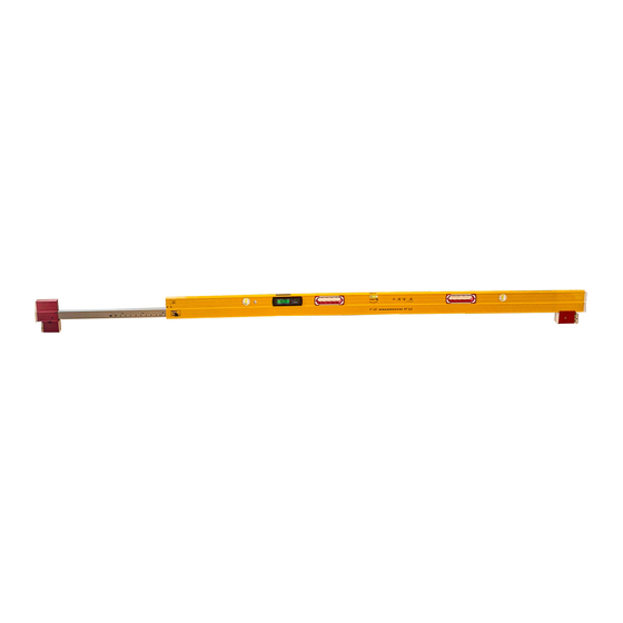
Congratulations on the purchase of your STABILA measuring tool. Read the safety instructions and operating instructions through carefully. The STABILA TECH 106 T is an electronic spirit level with 2 digital displays for measuring inclinations and angles. The telescopic extension enables an extremely large surface to be measured. -
Page 4: Components Of The Unit
TECH 106 T 3.1. Components of the unit Electronic module (dust-proof and waterproof in accordance with IP 65) Battery compartment lid 2 displays Vials – vertical and horizontal 2 measuring surfaces Telescopic extension with scales on both sides Snap-ins Clamping lever with spring-loaded bolt... -
Page 5: Buttons
TECH 106 T 3.2 Buttons: (11) On/Off (12) Units of measurement: °, %, mm/m, in/ft (13) Calibration and sensor adjustment (14) HOLD – locking measurements (15) Reference – freely selectable zero position (16) Acoustic guidance (17) Key lock (18) Display lighting 4. -
Page 6: Commissioning
TECH 106 T 5. Commissioning 5.1 Inserting batteries/battery replacement Unscrew battery compartment lid on rear, insert new batteries according to symbol in battery compartment. Suitable rechargeable batteries can also be used. The wedge in the battery door opposite the fastening... -
Page 7: Functions
TECH 106 T 6. Functions 6.1 Visual guidance In the range of ± 15° to the horizontal (0°) or to the vertical (90°), arrows show which way to turn the digital protractor to reach 0° or 90°. The 2 "center display" bars indicate the precise position at which 0°... -
Page 8: Acoustic Guidance
TECH 106 T 6.2 Acoustic guidance The acoustic guidance is activated/deactivated using the "Loudspeaker" button. The tone sequence speeds up as the 0° or 90° position is approached in a range of ± 2°. A change in the pitch indicates that these positions have been exceeded. -
Page 9: Setting The Mode Unit Of Measurement
TECH 106 T 6.4 Setting the MODE unit of measurement 0,05° The unit of measurement is set by pressing the "MODE" button several times. 0,1˚ ° Fine: Display in 0.01° steps ° Rough: Display in 0.1° steps Display in 0.1 %... -
Page 10: Freely Selectable Zero Position Ref
TECH 106 T 6.6 Freely selectable zero position REF REFERENCE 20° The "REF” button can be used to select any set angle as 0° reference. The angle details now displayed relate to this reference angle. The displayed value flashes with this setting. -
Page 11: Lighting
TECH 106 T 6.7 Lighting Briefly pressing the "Lighting" button switches the display ≥ 5 sec lighting on for approx. 60 seconds. ∞ on = 60 sec on = Pressing and holding (≥ 5 sec) the "Lighting" button makes the lighting darker and switches it on permanently. -
Page 12: Tilt Function
TECH 106 T 7. Tilt function 5° 5° The measuring surfaces of the electronic spirit level should be positioned precisely for all measurement work. If positioned/tilted in excess of 5°, the tilt function 5° 5° prevents incorrect measurements. The display doesn't... -
Page 13: Usage
TECH 106 T 8. Usage 8.1 Usage as telescopic spirit level The telescopic extension enables an extremely large surface to be measured. Using the clamping lever, the telescopic extension can be secured at any length. Scales on both sides facilitate quick presetting. -
Page 14: Grid Dimensions For The Frame Construction
TECH 106 T 8.3 Grid dimensions for the frame construction The snap-ins are positioned at the standard dimensions for a timber frame construction. The spring-loaded bolt on the eccentric clamp engages precisely. SNAP IN SNAP IN SNAP IN 11 6... -
Page 15: Placement In The Timber Frame
TECH 106 T 8.4 Placement in the timber frame Once the spirit level has been preset to the required grid dimension, place it in the timber frame with the spring element. The spring element must be compressed. Next, place the upper measuring surface of the telescopic extension in the frame. -
Page 16: Checking The Measuring Tool
TECH 106 T 9. Checking the measuring tool 9.1 Accuracy check To prevent incorrect measurements, the accuracy must be checked at regular inter- vals, e.g. before you start work, or after hard knocks or major changes in temperature. Step 1: Switch on the electronic spirit level. - Page 17 TECH 106 T 9.2 Calibration 1. Switch on the electronic spirit level. Use the vial to accurately align the unit to a wall, for example, until the vial bubble is in the middle between the vial rings. If mainly used for vertical measurements, the calibration can also be undertaken with the vertical vial.
-
Page 18: Adjusting The Sensor
TECH 106 T 9.3 Adjusting the sensor Calibration in 4 positions is needed if the following is displayed: 1. The reverse test angle is ≥ 0.1° to the normal position --> too great a deviation. 2. Change in internal reference 3. - Page 19 TECH 106 T 9.3 Adjusting the sensor Step 1: Simultaneously press the "MODE" and "CAL" buttons. Align the electronic spirit level accurately against a wall and press the CAL button to confirm. Step 1 must be performed with the vial. This ensures that the spirit level, the horizontal vial and the sensor are synchronised with each other.
- Page 20 TECH 106 T 9.3 Adjusting the sensor Step 2: The electronic spirit level is turned 180° and aligned using the arrows displayed. 180° The electronic spirit level is aligned horizontally using the arrows displayed. The 2 "center display" bars indicate the precise position at which the horizontal is reached.
- Page 21 TECH 106 T 9.3 Adjusting the sensor Step 3 The electronic spirit level is turned 90° and aligned vertically using the arrows displayed. The 2 "center display" bars indicate the precise position at which the vertical is reached. Confirm by pressing the CAL button.
- Page 22 TECH 106 T 9.3 Adjusting the sensor Step 4 The electronic spirit level is turned 180° and aligned vertically using the arrows displayed. The 2 "center display" bars indicate the precise position at which the vertical is reached. Confirm by pressing the CAL button.
-
Page 23: Error Messages
TECH 106 T 10. Error messages Display: Cal. /temperature The sensor must be adjusted if the temperature or Cal. symbols are indicated in the display. Display: Err The unit must not be moved or subjected to vibrations during the calibration/sensor adjustment. This can lead to measurement errors. -
Page 24: Technical Data
TECH 106 T 11. Technical data Accuracy: Electronic module 0° / 90° / 180° / 270° : ± 0,05° In intermediate areas ± 0,2° Spirit level in normal position: .029° = 0,5 mm / m in reverse position: .029° = 0,5 mm / m in extended normal position .057°...
Need help?
Do you have a question about the TECH 106 T and is the answer not in the manual?
Questions and answers