Advertisement
- 1 FUNCTIONS & FEATURES
- 2 INITIAL INSTALLATION
- 3 GETTING ACQUAINTED
- 4 MODE SET
-
5
BASIC OPERATIONS
- 5.1 Switching the Power On/Off
- 5.2 Adjusting the Volume
- 5.3 Adjusting Frequency
- 5.4 Adjust Channel
- 5.5 Receiving
- 5.6 Transmitting
- 5.7 Switch between Main Channel and Sub Channel
- 5.8 Switch between VFO and Channel Mode
- 5.9 Channel Edit
- 5.10 Channel Delete
- 5.11 CTCSS/DCS Encode and Decode Setup
- 5.12 CTCSS Scan
- 5.13 DCS Scan
- 5.14 Frequency/Channel Scan
- 5.15 Scan Skip
- 5.16 Squelch off/ Squelch off Momentary
- 5.17 KEYPAD LOCKOUT
- 5.18 Transmit DTMF/5 Tone Signaling
- 5.19 Transmit Tone burst frequency
- 5.20 Transmit DTMF by Microphone Keypad
-
6
FUNCTION MENU
- 6.1 Beep
- 6.2 Frequency Step Size Setup
- 6.3 Display mode setup
- 6.4 Squelch level Setup
- 6.5 Volume level setting
- 6.6 Password setting
- 6.7 Scan Dwell Time Setup
- 6.8 Scan Pause Time Setup
- 6.9 AOP (Automatic power on setup)
- 6.10 Dual Watch setup
- 6.11 Backlight Brightless Setup
- 6.12 TOT(Time Out Timer)
- 6.13 APO (Automatic Power OFF)
- 6.14 Pilot Frequency
- 6.15 DIR (LCD display direction setup)
- 6.16 Microphone Speaker
- 6.17 RTDF ( RX/TX dissimilar frequency Setup)
- 6.18 VOX FUNCTION SETTING
- 6.19 VOX-L:VOX Sensitivity setting
- 6.20 VOX-T: VOX Delay Time setting
- 6.21 Reset Factory Default
-
7
CHANNEL MENU
- 7.1 RCDT (CTCSS/DCS Decode Setup)
- 7.2 CTCSS/DCS Encode Setup
- 7.3 HIGH/MID/LOW Power Selection
- 7.4 5TENC (5TONE ENCODE SELECT)
- 7.5 T-DEC (Add Optional Signaling)
- 7.6 Signaling Combination Setup
- 7.7 Band-width Selection
- 7.8 Frequency Reverse
- 7.9 Talk Around
- 7.10 Offset Freqeuncy And Direction Setup
- 7.11 Editing Channel Name
- 7.12 Busy Channel Lockout
- 7.13 TX OFF
- 7.14 OWNID (SELF ID ENQUIRY)
- 8 KEYPAD MENU SETUP
- 9 DTMF SETTING
- 10 PROGRAMMING SOFTWARE INSTALLING AND STARTINGSOFTWARE I
- 11 MAINTENANCE
- 12 Trouble Shooting
- 13 SPECIFICATIONS
- 14 ATTACHED CHART
- 15 PRODUCT SAFETY GUIDE FOR TWO-WAY RADIOS
- 16 Documents / Resources
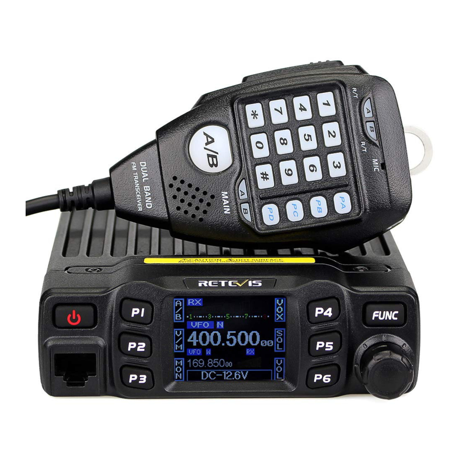
FUNCTIONS & FEATURES
RT95 Mobile Radio has nice housing, stoutness & stability, advanced and reliable functions, perfect & valuable. This amateur mobile radio especially designs for drivers and it pursues philosophy of innovation and practicality. More functions as follows:
- Adopt superior quality material, better technology and high quality radiator to ensure stable and durable operation;
- 180 degree rotatable TFT LCD display;
- Full alloy body for heat radiation;
- Frequency mode and Channel mode for different operation requirement;
- Distribute buttons reasonably, convenient for operation;
- Separate band width setting for each single channel, Wide 25K, Middle band 20K, Narrow band 12.5K;
- 200 programmable memory channels, identified by enditing name;
- Separate CTCSS, DCS, DTMF, 5Tone setting for each single channel, rejecting extra calling from other radios;
- Various scan functions including CTCSS/DCS Scan function;
- Smart menu control and PC programming control;
- Voltage level protection;
- LCD brightless control;
- Automatic power on function;
- Main unit and microphone key lock function;
- 5Tone signaling for data transfer, alarm, all call, ANI, remote kill, remotewaken.
- DTMF-ANI or 5Tone-ANI for automatical calling recognition;
- Scrambler(Optional).
INITIAL INSTALLATION
Mobile Installation
To install the transceiver, select a safe, convenient location inside your vehicle that minimizes danger to your passengers and yourself while the vehicle is in motion. Consider installing the unit at an appropriate position so that knees or legs will not strike it during sudden braking of your vehicle. Try to pick a well ventilated location that is shielded from direct sunlight.
- Install the mounting bracket in the vehicle using the supplied selftapping screws (2pcs) and flat washers (2pcs).

- Position the transceiver, then insert and tighten the supplied hexagon SEMS screws.
- Double check that all screws are tightened to prevent vehicle vibration from loosening the bracket or transceiver.

DC Power Cable Connection
![]()
- Locate the power input connector as close to the transceiver as possible.
Mobile Operation
The vehicle battery must have a nominal rating of 12V. Never connect the transceiver to a 24V battery. Be sure to use a 12V vehicle battery that has sufficient current capacity. If the current to the transceiver is insufficient, the display may darken during transmission, or transmitting output power may drop excessively.
- Route the DC power cable supplied with the transceiver directly to the vehicle's battery terminals using the shortest path from the transceiver.
- We recommend you do not use the cigarette lighter socket as some cigarette lighter sockets introduce an unacceptable voltage drop.
- The entire length of the cable must be dressed so it is isolated from heat, moisture, and the engine secondary (high voltage) ignition system/ cables.
- After installing cable, in order to avoid the risk of damp, please use heat-resistant tap to tie together with fuse box. Don't forget to reinforce whole cable.
- In order to avoid the risk of short circuit, please cut down connection with negative (-) of battery, then connect with radio.
- Confirm the correct polarity of the connections, then attach the power cable to the battery terminals; red connects to the positive (+) terminal and black connects to the negative (-) terminal.
- Use the full length of the cable without cutting off excess even if the cable is longerthan required. In particular, never remove the fuse holders from the cable.

- Use the full length of the cable without cutting off excess even if the cable is longerthan required. In particular, never remove the fuse holders from the cable.
- Reconnect any wiring removed from the negative terminal.
- Connect the DC power cable to the transceiver's power supply connector.
- Press the connectors firmly together until the locking tab clicks.

Fixed Station Operation
DC power supply, Please contact local dealer to require. The recommended current capacity of your power supply is 12A.
- Connect the DC power cable to the regulated DC power supply and ensure that the polarities are correct. (Red: positive, Black: negative).
- Do not directly connect the transceiver to an AC outlet.
- Use the supplied DC power cable to connect the transceiver to a regulated power supply.
- Do not substitute a cable with smaller gauge wires.

- Connect the transceiver's DC power connector to the connector on the DC power cable.
- Press the connectors firmly together until the locking tab clicks.

![]()
- Before connecting the DC power to the transceiver, be sure to switch the transceiver and the DC power supply OFF.
- Do not plug the DC power supply into an AC outlet until you make all connections.
Replacing Fuses
If the fuse blows, determine the cause, then correct the problem. After the problem is resolved, replace the fuse. If newly installed fuses continue to blow, disconnect the power cable and contact your authorized  dealer or an authorized servicecenter for assistance.

| Fuse Location | Fuse Current Rating |
| Transceiver 10A | 10A |
| Supplied Accessory DC power cable | 10A |
Only use fuses of the specified type and rating, otherwise the transceiver could be damaged.
![]()
- If you use the transceiver for a long period when the vehicle battery is not fully charged, or when the engine is OFF, the battery may become discharged, and will not have sufficient reserves to start the vehicle. Avoid using the transeceiver in these conditions.
Antenna Connection
Before operating, install an efficient, well-tuned antenna. The success of your installation will depend largely on the type of antenna and its correct installation. The transceiver can give excellent results if the antenna system and its installation are given careful attention. Use a 50 impedance antenna and low-loss coaxial feed-line that has a characteristic impdeance of 50,to match the transceiver input impedance, Coupling the antenna to the transceiver via feed-lines having an impedance other than 50 reduces the efficiency of the antenna system and can cause interference to nearby broadcast television receivers, radio receivers, and other electronic equipment.
![]()
- Transmitting without first connecting an antenna or other matched load may damage the transceiver. Always connect the antenna to the transceiver before transmitting.
- All fixed stations should be equipped with a lightning arrester to reduce the risk of fire, electric shock, and transceiver damage.
The possible locations of antenna on a car are shown as following:

Accessories Connections
External Speaker
If you plan to use an external speaker, choose a speaker with an impedance of 8.The external speaker jack accepts a 3.5mm (1/8") mono (2-conductor) plug.

![]()
- External speaker adopt double port BTL, please care about the connecting way.
The speaker can not connect with the ground, otherwise the speaker will be fault. The wrong connecting way as the following picture.


Microphone
For voice communications, connect a microphone equipped with an 8-pin modular plug into the modular socket on the front of the main unit. Press irmly on the plug until the locking tab clicks.

GETTING ACQUAINTED
Front panel

| NO. | Key | Funktion |
| 1 |  | Power On/Off/Mute |
| 2 |  | Self define key |
| 3 |  | Self define key |
| 4 |  | Self define key |
| 5 |  | Self define key |
| 6 |  | Self define key |
| 7 |  | Self define key |
| 8 |  | Function key/ function group key |
| 9 | MIC | Microphone Jack |
| 10 |  | Channel switch/Push button/Key lock |
| 11 | LCD display | Display channel/frequency/function setting |
Rear panel

| NO. | Key | Funktion |
| 1 | Antenna connector | Connect a 50 ohm antenna |
| 2 | Ex-Speaker Jack | Connect external speaker |
| 3 | Power cable | Connect a standard DC power cable |
Display

| NO. | Funktion |
| 1 | Displays the self define function when press P1 |
| 2 | Displays the self define function when press P2 |
| 3 | Displays the self define function when press P3 |
| 4 | Displays the self define function when press P4 |
| 5 | Displays the self define function when press P5 |
| 6 | Displays the self define function when press P6 |
| 7 | Displays the main channel TX or RX status |
| 8 | Displays when Automatic power off function is on |
| 9 | Displays the main channel field strength |
| 10 | Displays main channel number in channel mode |
| 11 | Displays when set band width for main channel |
| 12 | Displays when main channel set CTCSS/DCS |
| 13 | Displays when main channel reverse function is on |
| 14 | Displays when main channel offset function is on |
| 15 | Displays when main channel is in scan list |
| 16 | Displays main channel frequency or name |
| 17 | Displays sub channel number in channel mode |
| 18 | Displays when setting band width for sub channel |
| 19 | Displays when current sub channel set CTCSS/DCS |
| 20 | Displays when sub channel reverse function is ON |
| 21 | Displays when sub channel offset function is ON |
| 22 | Displays when sub channel receive a signal |
| 23 | Display sub channel frequency or name |
| 24 | Displays signal strength of sub channel |
| 25 | Display voltage and menu setting |
Microphone

| NO. | Key | Funktion |
| 1 | UP | Increase frequency, channel number or setting value |
| 2 | DOWN | DOWN Decrease frequency, channel number or setting value |
| 3 | PTT | PTT Press the PTT (Push-TO-Talk) key to transmit |
| 4 | Number Key | Number Key Input VFO frequency or DTMF dial out etc. |
| 5 | A/B band | A/B band Choose left band or right band as Main band |
| 6 | Band indicator | Band indicator The indicator light on for Main band |
| 7 | TX/RX indicator | TX/RX indicator Light green while receiving, Light red while transmitting |
| 8 | MIC | MIC Speak here during transmission |
| 9 | Speaker | Speaker When shut the speaker in the base, you can hear the calling by this speaker |
| 10 | Lock UP/DOWN | 10 Lock UP/DOWN When this key is in up position, It is unlock UP/DOWN key, when this key is in down poisition, UP/DOWN key will be locked |
MIC Connector Diagram(in the front view of connector)

MODE SET
Display Mode
How to choose display mode by PC programming: In PC software's "Function Setup" menu, the "Display Mode" selection available setting: "Frequency", "Channel" or "Name" How to choose display mode by radio menu: Please refer to "Display Mode".
- Frequency mode: When set display as'Frequency", new setting of channel operation and shortcut operation can be temporarily used by user. Once the radio is turned off or switched to another channel, the temporary setting will be erased and back to initial settings.(As pic 1)
(As pic 1)
![]()
- Channel Name Mode: When set display as "Name",it enters into Channel name mode. In this mode, it will display corresponding channel name when the current channel is edited with name. Otherwise, it will display frequency + channel number.
(As pic 2)
![]()
- Channel mode: When set display mode as "Channel", it enters channel mode. If there is name for current channel, the LCD will display current channel name otherwise it shows current channel number.(As pic 3)
(As pic 3)
![]()


Working Mode
How to choose work mode by PC programming: In PC software's "Function Setup" menu, the "VFO/MR A" and "VFO/MR B" selection available setting: "VFO","MR.".
- VFO Mode: This mode shows only frequency on the display. Shortcut operation and Channel setting will be changed & stored as the latest value. if the radio is turned off, the latest setting will not changed. In VFO mode, adjust the channel knob will adjust the frequency by pre-programmed step size.
- "MR." Mode: Memory mode, In this mode, the radio will work by pre-programmed channels, ajust the channel knob will move the channel up and down.
![]()
- If transceiver programmed as channel mode and locked, you can't return to frequency mode by manual operation in the radio menu.
BASIC OPERATIONS
Switching the Power On/Off
- Power On: in power off state press
![]() , the LCD displays " RETEVIS " then willdisplays current frequency or channel.
, the LCD displays " RETEVIS " then willdisplays current frequency or channel. - Power Off: in power on state, press
![]() for 2 seconds, the LCD displays "CLOSING",then the LCD display disappears.
for 2 seconds, the LCD displays "CLOSING",then the LCD display disappears.
Adjusting the Volume
- In standby mode, short press the [PX] key programmed as VOL control, the LCD display "VOL:XX", then turn the channel switch to adjust volume level.
- In standby mode, short press
![]() to mute the speaker, the LCD display "AUDIO:MT",short press it again to return last volume level.
to mute the speaker, the LCD display "AUDIO:MT",short press it again to return last volume level.
![]()
- During communication, volume level can be adjusted more accurate.
Adjusting Frequency
- By channel knob: In VFO mode, turn channel knob can adjust frequency, push channel knob, the matching charactor willflash, then turn channel knob to adjust the frequency by step size 1K, 10K, 100K, 1Mz or 10MHz.
![]()
- The microphone [UP]/[DOWN] key can also adjust the frequency, each press move one step size. hold the [DOWN] key can decrease one step size. if the channel knob is programmed as VOL function, users need press the PX key which programmed as FRQ function, when the LCD displays "VFO FREQ", turn channel knob to adjust frequency.
- By number key: In VFO mode, you can input wanted frequency by the microphone number key. For example if want 145.125Mhz, just press key 1, 4, 5, 1, 2, 5, if want 145Mhz, just press 1, 4, 5. The input is invalid if the frequency is over range.
Adjust Channel
- Adjust channel by channel switch: In channel mode, turn channel knob to adjust the channel, the [UP]/[DOWN] key in the microphone can also adjust the main channel.
![]()
- If there is an empty channel, the radio will jump over it to next channel. If the channel knob is programmed as VOL function, users need press the PX key which programmed as CH function, when the LCD displays "CH XX ", turn channel knob to adjust channel.
- By number key: In CH mode, you can input wanted channel by the microphone input 3 numbers (001-200), 001 stands for channel 1, 200 stands for channel 200. if input channel is an empty channel, the radio will report error and return to last channel.
Receiving
When the channel you are operating being called, the screen shows red RX and field strength in this way you can hear the calling.
![]()
- When the RX icon and field strength flashes, but can not hear the calling, it means current channel receive a matching carrier but unmatching signaling. Refer to CTCSS/ DCS CODE or Optional Signaling setup).
Transmitting
Hold [PTT] and speak into microphone. the radio start transmit, the screen shows red TX and field strength. Hold the microphone approximately 2.5-5.0cm from your lips and speak to microphone in your normal speaking voice to get best timbre.
![]()
- Only available transmit on main channel.
Switch between Main Channel and Sub Channel
This radio work by single channel dual watch, in standby, the frequency in the upper side is main channel and down side is sub channel, the transmit is available only on main channel.
- Short press [FUNC] to switch function group, choose the [PX] key defined as A/B function.
- Short press [PX] key defined as A/B function, then repratedly press this key or turn channel knob to switch main channel and sub channel, the LCD displays Main: XX.
- Hold [PUSH] or [FUNC] key to store and exit, or wait 10 seconds the radio will store the setting and exit.
Switch between VFO and Channel Mode
- Short press [FUNC] to switch function group, choose the [PX] key defined as V/M function.
- Short press [PX] key defined as V/M function, then repeat press this key or turn channel knob to switch main channel and sub channel, the LCD displays V/M:XX.
- Hold [PUSH] or[FUNC] key to store and exit, or wait 10 seconds the radio will store the setting and exit.
Channel Edit
- In VFO mode, turn channel knob or the [UP]/[DOWN] key in microphone to adjust frequency.
- Short press [FUNC] to switch function group, choose the [PX] key defined as CDT function. Press [PX] key defined as CDT function to set CTCSS/DCS code. turn channel knob or the [UP]/[DOWN] key in microphone to choose CTCSS/DCS code.
- Long press [FUNC] key to enter channel setting menu, to choose wanted setting.
- Short press [FUNC] key to switch function group, hold the [PX] key defined as V/M function until the channel number flashes, if the channel number is red means current channel is valid, if the channel number is green, means current channel is empty.
- Turn the channel knob or microphone [UP]/[DOWN] key to choose the channel number to be stored.
- Hold the [PX] key defined as V/M function to confirm and store the channel, the channel number stop flash and radio emits a beep sound, the channel is stored successfully.
Channel Delete
- In channel mode, turn the channel knob or microphone [UP]/[DOWN] key to choose an unwanted channel.
- Short ptess [FUNC] key to switch function group, choose the [PX] key defined as V/M function, press this key together with [FUNC] key for 2 seconds, current channel is deleted and automatical jump to next channel.
CTCSS/DCS Encode and Decode Setup
- Short press [FUNC] to switch function group, choose the [PX] key defined as CDT function.
- Short press PX defined as CDT function, then repearedly short press this key set the currently channel if use CTCSS/DCS encode and decode.
- When the LCD displays: RCDT:XXX, turn channel knob or press microphone [UP]/[DOWN] key to choose if add CTCSS/ DCS decode signaling to current channel. Press [PUSH] button then turn channel knob or press microphone [UP]/[DOWN] key to choose wanted CTCSS/DCS decode signaling.
- When the LCD displays: TCDT:XXX, turn channel knob or press microphone [UP]/[DOWN] key to choose if add CTCSS/ DCS encode signaling to current channel. Press [PUSH] button then turn channel knob or press microphone [UP]/[DOWN] key to choose wanted CTCSS/DCS encode signaling.
- CTCSS:62.5-254.1Hz plus one self define group. total 52 group.
DCS: 000N-777I total1024 groups.
N is positive code, I is inverse code.
Press FUNC key can choose positive or inverse code. - Hold [PUSH] or [FUNC] key to store and exit, or wait 10 seconds the radio will automatically store the setting and exit.
![]()
- Under channel mode, this operation can be temporarily used by user. Once the radio is turned off or switched to another channel, the temporary setting will be erased. If the channel setting programmed for valid, the temporary setting will keep valid until next change, turn off radio or switch to another channel, the temporary setting will not changed.
CTCSS Scan
In channel or VFO mode, short press [FUNC] to switch function group, choose the [PX] key defined as CDT funtion.short press this key to enter CTCSS code setting.when the LCD displays CTC, long press this key to enter CTCSS scan. turn channel knob or press microphone [UP]/[DOWN] key can change scan direction. Once finding a matching CTCSS signaling, it will stop 5 seconds then scan again, short press any key to exit CTCSS scan.
DCS Scan
In channel or VFO mode, short press [FUNC] to switch function group, choose the [PX] key defined as CDT function. short press this key to enter DCS code setting. When the LCD displays DCS, long press this key to enter DCS scan, turn channel knob or press microphone [UP]/[DOWN] key can change scan direction. Once finding a matching DCS signaling, it will stop 5 seconds then scan again, press any key to exit DCS scan.
Frequency/Channel Scan
Frequency Scan
In frequency (VFO) mode, this function is designed to monitor signal of all frequency points under each step size.
- In VFO mode, short press [FUNC] key to switch function group, choose the [PX] key defined as SCN function.
- Short press the [PX] key defined as SCN function to start frequency scan, the LCD displays "S".
- Turn channel knob or press microphone [UP[DOWN] key can change scan direction.
- Turn channel knob or press any key except microphone [UP][DOWN] key to exit.
Channel Scan
In channel mode, this function is designed to monitor signal of all channel.
- In channel mode, press [FUNC] key to switch function group, choose the [PX] key defined as SCN function.
- Short press the [PX] key defined as SCN function to start channel scan, the LCD displays: S.
- Turn channel knob or press microphone [UP][DOWN] key can change scan direction.
- Turn channel knob or press any key except microphone [UP]/[DOWN] key to exit.
Scan Skip
In channel mode, press [FUNC] key to switch function group, choose the [PX] key defined as SCN function. Hold this key to add into or delete from scan list.
- When LCD displays: S, the current channel is in scan list.
- When LCD not displays: S, the current channel is not in scan list.
Squelch off/ Squelch off Momentary
The [PX] key defined as MON function, can monitor the weak signal.
- Press [FUNC] key to switch function group, choose the [PX] key defined as MON function.
- Short press the [PX] key defined as MON function to turn squelch off / squelch off momentary, the LCD displays red "RX" icon.
Squelch off: press the [PX] key defined as MON to disable squelch, press [MON] key to resume squelch.
Squelch off momentary: hold the [PX] key defined as MON to disable squelch, release [MON] key to resume squelch.
KEYPAD LOCKOUT
Avoiding unintentional operation, this function will lock the keys except [PTT], [PUSH], ![]() Keys.
Keys.
- Long press [PUSH] button, the downside of the LCD displays Key Lock, means the keypad is locked.
- Long press [PUSH] button again, the downside LCD displays: Key Unlock, means the keypad is unlocked.
![]()
- NOTE:When keypad lockout, except
![]() key, [PUSH] button and [PTT] key is available, other keys are invalid.
key, [PUSH] button and [PTT] key is available, other keys are invalid.
Transmit DTMF/5 Tone Signaling
If the current channel is with DTMF/5TONE signaling, hold PTT and [UP] key will transmit selected Pre-programmed signaling.
Transmit Tone burst frequency
Hold PTT and [DOWN] key will transmit selected Pre-programmed tone burst frequency.
Transmit DTMF by Microphone Keypad
Hold PTT, then input DTMF signaling by the microphone keypad.
FUNCTION MENU
- Hold [FUNC] key to enter SELECT MENU interface.
- Short press [P4], [P6] key or turn channel knob to choose menu list. Short press [P5] can fast turn page.
- Press [PUSH] button to enter FUNC MENU setting.
- Short press [P4], [P6] key or turn channel knob to choose wanted setting.
Beep
- Enter FUNCTION MENU list, choose No.01 function.
- Press [PUSH] button, the menu value in LCD turns to green color.
- Turn channel knob to choose wanted setting. Off~5: 6 levels available. Off: Turn off BEEP function.
- Press [PUSH] button or [P3] key to store setting and exit.
Frequency Step Size Setup
- Enter FUNCTION MENU list, choose No.02 function.
- Press [PUSH] button, the menu value in LCD turns to green color.
- Turn channel knob to choose wanted setting.
Total 9 Channel step size available: 2.5K,5K,6.25K,10K,12.5K,20K,25K, 30K and 50K. - Press [PUSH] button or [P3] key to store setting and exit.
Display mode setup
This radio has 3 different display: Frequency+Channel and Channel name Tag mode.
- Enter FUNCTION MENU list, choose No.03 function.
- Press [PUSH] button, the menu value in LCD turns to green color.
- Turn channel knob to choose wanted setting.
FRQ: Frequency+Channel mode.
CH: Channel mode.
NM: Channel+name mode+ Channel mode, If channel not named, it displays Fequency + Channel mode, otherwise displays the channel name. - Press [PUSH] button or [P3] key to store setting and exit.
Squelch level Setup
This function use for setting RX signal strength, the calling will be heard only when reach setted level, otherwise the radio will keep mute.
- Enter FUNCTION MENU list, choose No.04 function.
- Press [PUSH] button, the menu value in LCD turns to green color.
- Turn channel knob to choose wanted setting.
Off-9: Total 10 levels, OFF is lowest level, squelch is off. - Press [PUSH] button or [P3] key to store setting and exit.
Volume level setting
- Enter FUNCTION MENU list, choose No.05 function.
- Press [PUSH] button, the menu value in LCD turns to green color.
- Turn channel knob to choose wanted setting.1-36: total 36 levels available.
- Press [PUSH] button or [P3] key to store setting and exit.
Password setting
After enable this function, must be input correct password then can turn on the transceiver.
- Enter FUNCTION MENU list, choose No.06 function.
- Press [PUSH] button, the menu value in LCD turns to green color.
- Turn channel knob to choose wanted setting.
ON: Turn on password function.
OFF: Turn off password function. - Press [PUSH] button or [P3] key to store setting and exit.
Scan Dwell Time Setup
- Enter FUNCTION MENU list, choose No.07 function.
- Press [PUSH] button, the menu value in LCD turns to green color.
- Turn channel knob to choose wanted setting.
TO: It pause for preset pause time when scanning a matching signal, then resume scan.
CO: It pauses once scanning a matching signal, and resume scan when signal disappears.
SE: It stops once scanning a matching signal. - Press [PUSH] button or [P3] key to store setting and exit.
Scan Pause Time Setup
- Enter FUNCTION MENU list, choose No.08 function.
- Press [PUSH] button, the menu value in LCD turns to green color.
- Turn channel knob to choose wanted setting.
5S: It pauses 5s once scanning a matching signal, then resume scan.
10S: It pauses 10s once scanning a matching signal, then resume scan.
15S: It pauses 15s once scanning a matching signal, then resume scan. Press [PUSH] button or [P3] key to store setting and exit.
AOP (Automatic power on setup)
When turn off AOP, the radio need press ![]() key to power on when connect with the power supply.
key to power on when connect with the power supply.
- Enter FUNCTION MENU list, choose No.09 function.
- Press [PUSH] button, the menu value in LCD turns to green color.
- Turn channel knob to choose wanted setting.
ON: Enable AOP function.
OFF: Power off by manual. - Press [PUSH] button or [P3] key to store setting and exit.
Dual Watch setup
- Enter FUNCTION MENU list, choose No.10 function
- Press [PUSH] button, the menu value in LCD turns to green color.
- Turn channel knob to choose wanted setting
ON: Enable Dual Watch function
OFF: Disable Dual Watch function - Press [PUSH] button or [P3] key to store setting and exit.
Backlight Brightless Setup
- Enter FUNCTION MENU list, choose No.11 function
- Press [PUSH] button, the menu value in LCD turns to green color.
- Turn channel knob to choose brightless level, 1-3 level available.
- Press [PUSH] button or [P3] key to store setting and exit.
TOT(Time Out Timer)
The time-out timer limits continuous transmitting time. When transmit time last over programmed value, the transmitting will stop and emit a prompt.
- Enter FUNCTION MENU list, choose No.12 function
- Press [PUSH] button, the menu value in LCD turns to green color
- Turn channel knob to choose wanted setting.
1-30: 1-30 minutes range available by 1 minute/step
OFF: Turn off TOT function - Press [PUSH] button or [P3] key to store setting and exit.
APO (Automatic Power OFF)
Once APO is activated, the transceiver will be automatically switched off when the pre-set timer running out.
- Enter FUNCTION MENU list, choose No.13 function.
- Press [PUSH] button, the menu value in LCD turns to green color.
- Turn channel knob to choose wanted setting.
30Min: Automatical power off after 30 minutes.
60Min: Automatical power off after 60 minutes.
120Min: Automatical power off after 120 minutes.
OFF: Automatical power off function is off. - Press [PUSH] button or [P3] key to store setting and exit.
Pilot Frequency
This function uses to start repeater. It needs a certain intensity Pilot Frequency to start dormant repeater. As usual, no need to send pilot frequency again once repeater started.
- Enter FUNCTION MENU list, choose No.14 function.
- Press [PUSH] button, the menu value in LCD turns to green color.
- Turn channel knob to choose wanted setting.
1000Hz: Pilot frequency 1000Hz
1450Hz: Pilot frequency 1450Hz
1750Hz: Pilot frequency 1750Hz
2100Hz: Pilot frequency 2100Hz - Press [PUSH] button or [P3] key to store setting and exit.
DIR (LCD display direction setup)
- Enter FUNCTION MENU list, choose No.15 function.
- Press [PUSH] button, the menu value in LCD turns to green color.
- Turn channel knob to choose wanted setting.
FAIL: Revers display.
STAN: normal display. - Press [PUSH] button or [P3] key to store setting and exit.
Microphone Speaker
- Enter FUNCTION MENU list, choose No.16 function.
- Press [PUSH] button, the menu value in LCD turns to green color
- Turn channel knob to choose wanted setting.
M&H: Turn on Main speaker and microphone speaker.
MAIN: Turn on Main speaker.
HAND: Turn on microphone speaker. - Press [PUSH] button or [P3] key to store setting and exit
RTDF ( RX/TX dissimilar frequency Setup)
This radio has dissimilar frequency function, when this function is on the frequency in upside of LCD is RX frequency, and the downside frequency is TX frequency. You can revise the RX frequency by numberic key in microphone, you can revise TX frequency by the A/B key in microphone or the PX dey defined as A/B function.
- Enter FUNCTION MENU list, choose No.17 function.
- Press [PUSH] button, the menu value in LCD turns to green color.
- Turn channel knob to choose wanted setting.
ON: Turn on RTDF function.
OFF: Turn off RTDF function - Press [PUSH] button or [P3] key to store setting and exit.
![]()
- Only can turn on RTDF function in VFO mode.
VOX FUNCTION SETTING
- Enter into FUNC Menu, select menu 18.
- Press PUSH to enter into menu setting, the menu value in LCD turns to green color.
- Turn Channel knob to choose wanted setting.
ON: Enable VOX
OFF: Disabe VOX - Press [PUSH] button or [P3] key to store setting and exit.
VOX-L:VOX Sensitivity setting
- Enter into FUNC Menu, select menu 19.
- Press [PUSH] to enter into menu setting, the menu value in LCD turns to green color.
- Turn Channel knob to choose wanted setting.
1: high level
9: low level - Press [PUSH] button or [P3] key to store setting and exit.
VOX-T: VOX Delay Time setting
- Enter into FUNC Menu, select menu 20.
- Press [PUSH] to enter into menu setting, the menu value in LCD turns to green color.
- Turn Channel knob to choose wanted setting.
1: short delay time
9: long delay time - Press [PUSH] button or [P3] key to store setting and exit.
Reset Factory Default
If you radio seems to be malfunctioning because of wrong operation or setup, this function will be able to resume all setup and channels to factory default.
- Enter FUNCTION MENU list, choose No.21 function.
- Press [PUSH] button, the menu value in LCD turns to green color.
- Turn channel knob to choose wanted setting.
ALL: All channel, signaling function setup resume factory default.
OPT: All function menu setup resume factory default except CHAN MENU. - Press [PUSH] button or [P3] key to store setting and exit.
CHANNEL MENU
- Hold [FUNC] key to enter SELECT MENU interface.
- Short press [P4] key, [P6] key or turn channel knob to choose menu list. Short press [P5]. key can fast turn page.
- Press [PUSH] button to enter CHAN MENU list.
- Short press [P4],[P6] key or turn channel knob to choose wanted setting.
RCDT (CTCSS/DCS Decode Setup)
- Enter CHAN MENU, choose No.1 function.
- Press [PUSH] button, the menu value in LCD turns to green color.
- Turn channel knob to choose wanted setting. OFF: Turn off CTCSS/DCS decode.
CTCSS: Choose CTCSS decode.
DCS: Choose DCS decode. - When choose CTCSS/DCS decode, press [PUSH] button to enter CTCSS/DCS decode setup, then turn channel knob to choose wanted CTCSS/DCS decode.
DCS: 000N-777I, total 1024 groups. N is positive code, I is inverse code.
Press [FUNC] key can choose positive or inverse code. - Press [PUSH] button or [P3] key to store setting and exit.
![]()
- The working of CTCSS/DCS decode shall be work associated with the squelch mode setup. (Refer to Signaling Combination setup in
CTCSS/DCS Encode Setup
- Enter CHAN MENU, choose No.2 function
- Press [PUSH] button, the menu value in LCD turns to green color.
- Turn channel knob to choose wanted setting. OFF: Turn off CTCSS/DCS encode.
CTCSS: Choose CTCSS encode.
DCS: Choose DCS encode. - When choose CTCSS/DCS encode, press (PUSH) button to enter CTCSS/DCS encode setup, then turn channel knob to choose wanted CTCSS/DCS encode.
CTCSS:62.5-254.1HZ,and one self-define group, total 52 groups. DCS: 000N-777I, total 1024 groups N is positive code, I is inverse code. - Press [PUSH] button or [P3] key to store setting and exit.
HIGH/MID/LOW Power Selection
- Enter CHAN MENU, choose No.3 function.
- Press [PUSH] button, the menu value in LCD turns to green color.
- Turn channel knob to choose wanted setting.
HI: Choose high power level.
MI: Choose middle power level.
LO: Choose low power level. - Press [PUSH] button or [P3] key to store setting and exit.
5TENC (5TONE ENCODE SELECT)
- Enter CHAN MENU, choose No.4 function;
- Press [PUSH] button, the menu value in LCD turns to green color.
- Turn channel knob to choose wanted setting.
0~99: Total 100 groups 5Tone encode for selection. - Press [PUSH] button or [P3] key to store setting and exit.
![]()
- 5Tone group name and connect shall be programmed by PC software. If the choose 5Tone encode has a group name, the LCD will display group name only.
T-DEC (Add Optional Signaling)
This transceiver has 2 optional signaling: DTMF/5Tone/. those signaling function similar to CTCSS/DCS signaling. When the receiver adds an optional signaling, the caller shall transmit matching signaling. DTMF and 5Tone signaling can be applied for other advanced features such as ANI, PTT ID, group call, select call, remotely stun, remotely kill waken...etc.
- Enter CHAN MENU, choose No.4 function.
- Press [PUSH] button, the menu value in LCD turns to green color.
- Turn channel knob to choose wanted setting. DT: means DTMF signaling is added.
5T: means DTMF signaling is added.
OFF: Turn off optional signaling. - Press [PUSH] button or [P3] key to store setting and exit.
![]()
- The working of optional signaling shall be work associated with the squelch mode setup. (Refer to Squelch Mode setup in page XX ).
Signaling Combination Setup
This function can improve the level of blocking irrelative signals.
- Enter CHAN MENU, choose No.6 function.
- Press [PUSH] button, the menu value in LCD turns to green color.
- Turn channel knob to choose wanted setting.
SQ:You can hear the calling when receive a mathcing carrrier.
CDT:You can hear the calling when receive a matchng carrier and CTCSS or DCS signaling.
TONE: You can hear the calling when receives matching carrier + optional signaling.
C&T: You can hear the calling when receives matching carrier + CTCSS/DCS + optional signaling.
C/T: You can hear the calling when receives any matching carrier or CTCSS/DCS or optional signaling. - Press [PUSH] button or [P3] key to store setting and exit.
![]()
- This settting is valid only when CTCSS/DCS signaling added.
Band-width Selection
Select suitable bandwidth in accordance with different local conditions
- Enter CHAN MENU list, choose No.7 function
- Press [PUSH] button, the menu value in LCD turns to green color.
- Turn channel knob to choose wanted setting.
WID: band width is 25k(Wide band)
MID: band width is 20k(Middle band)
NAR: band width is 12.5k(Narrow band) - Press [PUSH] button or [P3] key to store setting and exit.
Frequency Reverse
With this function on, the transceiver will be able to communicate with a transceiver in same network without through a repeater.
- Enter CHAN MENU list, choose No.8 function
- Press [PUSH] button, the menu value in LCD turns to green color.
- Turn channel knob to choose wanted setting.
ON: Turn on reverse function
OFF: Turn off reverse function - Press [PUSH] button or [P3] key to store setting and exit
![]()
- Frequency reverse is turn on, the TX and RX frequency will be exchanged, the CTCSS or DCS signaling also will be exchanged if existed in current channel.
Talk Around
- Enter CHAN MENU list, choose No.9 function
- Press [PUSH] button, the menu value in LCD turns to green color.
- Turn channel knob to choose wanted setting
ON: Turn on talk around function
OFF: Turn off talk around function - Press PUSH button or P3 key to store setting and exit.
![]()
- This function is hide when RTDF function is on.
Offset Freqeuncy And Direction Setup
- Enter CHAN MENU list, choose No.10 function
- Press [PUSH] button, the menu value in LCD turns to green color.
- Turn channel knob to choose wanted setting, press [FUNC] key to set the offset direction.
-: Minus offset, means transmitting frequency lower than receiving frequency.
+: Plus offset, means transmitting frequency higher than receiving frequency. OFF: OFFSET is turn off.
VHF: 0 - 38 Mhz frequency avaiable.
UHF: 0 - 90 Mhz frequency avaiable. - Press [PUSH] button or [P3] key to store setting and exit.
![]()
- OFFSET frequency is adjusted according to step size setup. This function is hide when RTDF function is on.
Editing Channel Name
After edit a name for a channel, if the display mode is channel name, the radio will display the name edited in this menu. Otherwise it will display the frequency.
- Enter CHAN MENU list, choose No.11 function
- Press [PUSH] button, the menu value in LCD turns to green color.
- Turn channel knob to choose wanted setting. Press [PUSH] to confirm and enter editing for next charactor.
- Press [PUSH] button or [P3] key to store setting and exit.
![]()
- In Frequency (VFO) mode or RTDF function is on. ,this function will be auto-hidden.
Busy Channel Lockout
Busy channel lockout is disable transmitting, once the channel is busy and you press [PTT], the raido will beep as warning and get back to receiving.
- Enter CHAN MENU list, choose No.12 function
- Press [PUSH] button, the menu value in LCD turns to green color.
- Turn channel knob to choose wanted setting.
BU: Signaling busy lockout, transmitting is inhibited when current channel receives a matching carrier.
RL: Signaling busy lockout, transmitting is inhibited when current channel receives a matching carrier but dis-matching CTCSS/DCS code.
OFF: Busy channel lockout is disabled. Transmitting is allowed in any receiving status - Press [PUSH] button or [P3] key to store setting.
TX OFF
- Enter CHAN MENU list, choose No.13 function
- Press [PUSH] button, the menu value in LCD turns to green color.
- Turn channel knob to choose wanted setting.
ON: TX allowed, press [PTT] to transmit
OFF: TX not allowed, only work in RX mode, press [PTT] will emit a beep. - Press [PUSH] button or [P3] key to store setting and exit
OWNID (SELF ID ENQUIRY)
- Enter CHAN MENU list, choose No.14 function;
- The LCD will display current channel DTMF ID or 5Tone ID.
KEYPAD MENU SETUP
Main unit keypad menu setup
- Hold [FUNC] key to enter SELECT MENU interface.
- Short press [P4] key, [P6] key or turn channel knob to choose menu list. Short press [P5] can fast turn page.
- Press [PUSH] button to enter MINI KEY menu list.
- Turn channel knob to choose wanted setting.
- Short press [PUSH] button to choose wanted keypad group.
- Short press [P1]~[P6] key to choose wanted self-define key.
- Press [FUNC] to confirm and exit.
H-DIM Microphone keypad backlight setup
- Hold [FUNC] key to enter SELECT MENU interface.
- Short press [P4] key, [P6] key or turn channel knob to choose menu list. Short press [P5] can fast turn page.
- Press [PUSH] button to enter HANDY KEY menu list.
- Short press [P4] key, [P6] key or turn channel knob to choose wanted setting.
Microphone keypad backlight brightness Setup
- Hold [FUNC] key to enter SELECT MENU interface.
- Short press [P4] key, [P6] key or turn channel knob to choose menu list. Short press [P5] key can fast turn page.
- Press [PUSH] button to enter HAND KEY menu list, choose No.1 function, press [PUSH] key to enter value setting, the menu value in LCD turns to green color.
- Turn channel knob to choose wanted setting, the microphone keypad has OFF-31, total 32 brightness levels. OFF means turn off backlight brightness.
- Press [PUSH] button or [P3] key to store setting and exit.
H-PA H-PD Microphone self-define keypad setup
- Hold [FUNC] key to enter SELECT MENU interface
- Short press [P4] key, [P6] key or turn channel knob to choose menu list. Press [P5] can fast turn page.
- Press [PUSH] button to enter HANDY KEY menu list.choose NO.2-5 function, then press [PUSH] button to enter value setting. the menu value in LCD turns to green color.
- Turn channel knob to choose wanted setting.
- Press [PUSH] button or [P3] key to store setting and exit.
DTMF SETTING
DTMF Encode group setting
- Enter DTMF menu. choose No.1 function
- Press [PUSH] button, the menu value in LCD turns to green color.
- Turn channel knob to choose wanted setting.1-16 total 16 groups DTMF encode for selection.
- If choosed group is empty, Press PUSH to edit DTMF code, the LCD displays "= = = = = = = =".
- Turn channel knob to choose wanted characator, press PUSH to confirm and move to next characator selection.
- Press [P3] key to store setting and exit.
DTMF Encode Transmitting Time
- Enter DTMF menu. choose No.2 function
- Press [PUSH] button, the menu value in LCD turns to green color.
- Turn channel knob to choose wanted setting.
50MS: The time for transmit a single DTMF encode and the interval is 50MS,
100MS: The time for transmit a single DTMF encode and the interval is 100MS,
200MS: The time for transmit a single DTMF encode and the interval is 200MS,
300MS: The time for transmit a single DTMF encode and the interval is 300MS, 500MS: The time for transmit a single DTMF encode and the interval is 500MS. - Press [PUSH] button or [P3] key to store setting and exit.
PROGRAMMING SOFTWARE INSTALLING AND STARTINGSOFTWARE I
Install USB Cable Driver Programme
- Click start menu in computer, under "ALL PROGRAMS" menu, choose and click "USB To Com port" in MT95 program, install "USB To Com port" driver by indication.
- Connect the optional USB Programming cable to USB port in PC with transceiver.
- Double click MT95 shortcut or click MT95 inprocedure index of start menu, choose serial com port as indicated then click OK to start programming software.
- According to instruction, select correct"COM Port", then click "OK" to start programming software.
![]()
- Even in same computer, the selective COM Port is different when USB cable connects with different USB port.
You shall install software before connecting the USB cable line. Switch on transceiver before writing frequency. You had better not switch on or off the power supply of transceiver when it is connected with computer, otherwise, it will make transceiver unable to read or write frequency. In this case, you have to turn off programming software, pull out USB cable. then reinsert USB cable and open software, then rechoose COM Port, it will turn into normal operation. Therefore, please connect transceiver with computer after switching on the transceiver. Don't restart transceiver power when it is connected with computer.
MAINTENANCE
Default Setting after Reset
| Frequency band | VHF | UHF |
| VFO frequency | 145.150MHz | 431.150MHz |
| Memory channel | -- | -- |
| Offset direction | -- | -- |
| Offset frequency | 600KHz | 5KHz |
| Channel step | 10KHz | 10KHz |
| CTCSS encode and decode | -- | -- |
| CTCSS tone frequency | 88.5Hz | 88.5Hz |
| DCS encode and decode | -- | -- |
| DCS Code | 000N | 000N |
| Output power | HI | HI |
| TOT | 3 | 3 |
| APO | OFF | OFF |
| VOL | 28 | 28 |
| Squelch Level | 3 | 3 |
Trouble Shooting
| Problem | Possible Causes and Potential Solutions |
Power is on, nothing appears on Display | + and - polarities of power connection are reversed. Connect red lead to plus terminal and black lead to minus terminal of DC power supply |
Fuse is blown | Check and solve problem resulting in blown fuse and replace fuse with new fuse |
No sound comes from speaker |
|
Key and Dial do not function | Key-lock function is activated. Cancel Key-lock function |
No Scan | Did not list the channel in the scan when programmed |
The whole band with noise after programmed | The squelch has opened during programmed |
Communication range was short, bad sensitivity |
|
Can not talk with other members within the group |
|
SPECIFICATIONS
| GENERAL | |
| Frequency Range | EU VHF: 144-146MHz UHF: 430~440MHz US VHF: 144-148MHz UHF: 430~440MHz |
| Number of Channels | 200 channels |
| Channel Spacing | 25K (Wide Band) 20K(Middle Band) 12.5K (Narrow band) |
| Phase-locked Step | 2,5KHz 5KHz 6,25KHz 10KHz 12,5KHz 20KHz, 25KHz 30KHz, 50KHz |
| Operating Voltage | 13.8V DC ±15% |
| Squelch | Carrier/CTCSS/DCS |
| Frequency Stability | ±2.5 ppm |
| Operating Temperature | -20~+60 |
| Dimensions(mm) | 124 (W) x 163(D) x 39 (H) |
| Weight | about 0.64Kg |
![]()
- Specifications are subject to change without notice due to advancements in technology.
| RECEIVER | ||
| Wide band | Narrow band | |
| Sensitivity (12dB Sinad) | ≤0.25μV | ≤0.35μV |
| Adjacent Channel Selectivity | ≥60dB | ≥60dB |
| Audio Response | +1~-3dB(0.3~3KHz) | +1~-3dB(0.3~2.55KHz) |
| Hum & Noise | ≥45dB | ≥40dB |
| Audio distortion | ≤5% | |
| Audio power output | >2W@8 | |
| TRANSMITTER | ||
| Wide band | Narrow band | |
| Power Output | 25W / 15W / 5W | |
| Modulation | 16KΦF3E | 11KΦF3E |
| Adjacent Channel Power | ≥70dB | ≥60dB |
| Hum & Noise | ≥70dB | ≥36dB |
| Spurious Emission | ≥40dB | ≥60dB |
| Audio Response | +1~-3dB(0.3~3KHz) | +1~- 3dB(0.3~2.55KHz) |
| Audio Distortion | ≤5% | |
ATTACHED CHART
52 groups CTCSS Tone Frequency(Hz)
")
1024 groups DCS Code
 - Table 1")
 - Table 2")
PRODUCT SAFETY GUIDE FOR TWO-WAY RADIOS
 ATTENTION! | Before using this radio, read this guide which contains important operating instructions for safe usage and rf energy awareness and control for compliance with applicable standards and regulations. |
- User instructions should accompany the device when transferred to other users.
- Do not use this device if the operational requirements described herein are not met.
Hand-held Mode(if applicable)

- Hold the radio in a vertical position with the microphone (and other parts of the radio including the antenna) at least 2.5 cm (one inch) away from the nose or lips. The antenna should be kept away from the eyes. Keeping the radio at a proper distance is important as RF exposure decreases with increasing distance from the antenna.
Phone Mode(if applicable)
- When placing or receiving a phone call, hold your radio product as you would a wireless telephone. Speak directly into the microphone. Do not use the equipment when you are driving
Avoid Choking Hazard

Small Parts. Not for children under 3 years.
Turn off your radio power in the following conditions:

- Turn off your radio before removing (installing) a battery or accessory or when charging battery.
- Turn off your radio when you are in a potentially hazardous environments: Near electrical blasting caps, in a blasting area, in explosive atmospheres (inflammable gas, dust particles, metallic powders, grain powders, etc.).
- Turn off your radio while taking on fuel or while parked at gasoline service stations. To avoid electromagnetic interference and/or compatibility conflicts
- Turn off your radio in any facility where posted notices instruct you to do so, hospitals or health care facilities (Pacemakers, Hearing Aids and Other Medical Devices) may be using equipment that is sensitive to external RF energy.
- Turn off your radio when on board an aircraft. Any use of a radio must be in accordance with applicable regulations per airline crew instructions.
Protect your hearing:

- Use the lowest volume necessary to do your job.
- Turn up the volume only if you are in noisy surroundings.
- Turn down the volume before adding headset or earpiece.
- Limit the amount of time you use headsets or earpieces at high volume.
- When using the radio without a headset or earpiece, do not place the radio's speaker directly against your ear
- Use careful with the earphone maybe possible excessive sound pressure from earphones and headphones can cause hearing loss
Note: Exposure to loud noises from any source for extended periods of time may temporarily or permanently affect your hearing. The louder the radio's volume, the less time is required before your hearing could be affected. Hearing damage from loud noise is sometimes undetectable at first and can have a cumulative effect.
Avoid Burns
Antennas
- Do not use any portable radio that has a damaged antenna. If a damaged antenna comes into contact with the skin when the radio is in use, a minor burn can result.
Batteries (If appropriate)
- When the conductive material such as jewelry, keys or chains touch exposed terminals of the batteries, may complete an electrical circuit (short circuit the battery) and become hot to cause bodily injury such as burns. Exercise care in handling any battery, particularly when placing it inside a pocket, purse or other container with metal objects
- BATTERY WARNING: KEEP OUT OF REACH OF CHILDREN
- Store spare batteries securely
- If the battery compartment (if applicable) does not close securely, stop using the product and keep it away from children
- If you think batteries might have been swallowed or placed inside any part of the body, seek immediate medical attention
- Dispose of used batteries immediately and safely
Long transmission
- When the transceiver is used for long transmissions, the radiator and chassis will become hot.
Safety Operation
Forbid
- Do not use charger outdoors or in moist environments, use only in dry locations/conditions.
- Do not disassemble the charger, that may result in risk of electrical shock or fire.
- Do not operate the charger if it has been broken or damaged in any way.
- Do not place a portable radio in the area over an air bag or in the air bag deployment area. The radio may be propelled with great force and cause serious injury to occupants of the vehicle when the air bag inflates.
To reduce risk
- Pull by the plug rather than the cord when disconnecting the charger.
- Unplug the charger from the AC outlet before attempting any maintenance or cleaning.
- Contact Retevis for assistance regarding repairs and service.
- The adapter shall be installed near the equipment and shall be easily accessible
Approved Accessories
- This radio meets the RF exposure guidelines when used with the Retevis accessories supplied or designated for the product. Use of other accessories may not ensure compliance with the RF exposure guidelines and may violate regulations.
- For a list of Retevis-approved accessories for your radio model, visit the following website: http://www.Retevis.com
Documents / Resources
References
Download manual
Here you can download full pdf version of manual, it may contain additional safety instructions, warranty information, FCC rules, etc.
Advertisement


Need help?
Do you have a question about the RT95 and is the answer not in the manual?
Questions and answers