Advertisement
Table of Contents
Advertisement
Table of Contents

Related Manuals for Retevis RA87


Summary of Contents for Retevis RA87
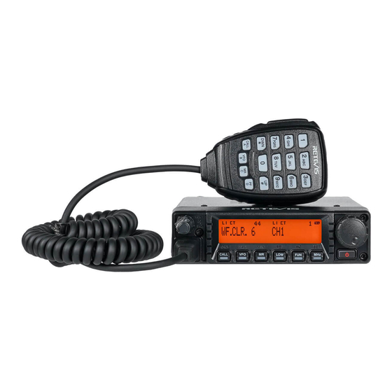
- Page 1 RA87 GMRS Mobile Radio USER’S MANUAL...
-
Page 2: Table Of Contents
CONTENT To customers................. Main Features................Radio Function................Preparations.................. Basic Operations................Menu Settings................Memory Channel................Scan....................CTCSS/DCS................... Repeater Function and Form............DTMF Function................2 TONE Signaling................MSK Signaling................Additional Function..............Reset Operation................ -
Page 3: To Customers
To customers Thank you for using Retevis mobile radio. This product has a newly upgraded menu and adopts humanized design, making it easy to use. It will meet your requirement with the compact size and reasonable price. Main Features Control and select various functions conveniently through the menu. - Page 4 Display Lists Choose RF power levels Appear when DCS/CTCSS function is activated. Appear when 2TONE function is activated. Appear when repeater station offset function is activated. Display menu numbers, memory channel numbers and status. Appear when data appearing in displayed memory channel. Display frequency, menu setting, memory name and other information.
-
Page 5: Preparations
Microphone List Name Function PTT Key Press the key to transmit signals and release to receive signals. DWN/*Key Press the key to decrease operating frequency, memory channel numbers, menu numbers, etc. Continuously press to repeat operations. For multi-choice functions, the key can switch different values. Press microphone PTT key, then press DWN/* key to transmit. -
Page 6: Basic Operations
2.Connect the DC power cable to the power connector of mobile radio 3.Replace Fuse Wire: If the fuse wire is fusing, confirm the reason and problems, then replace fuse wire. 4.Antenna Connection: As the figure shown: connect the antenna connector and the mobile radio (Note: ensure the connection between mobile radio and antenna is completed before transmitting). -
Page 7: Menu Settings
Main Frequency and Sub-frequency Switch Main frequency refers to the current operating and working channel. Sub-frequency refers to the receiving and monitor channel. 3 methods to switch main frequency and sub-frequency 1.When menu 14(ECHO) is set to "AUTO", the secondary frequency of the monitored signal automatically switches to the main frequency. 2. - Page 8 Menu Function List Screen Menu Function Selection Default Reference Display Number Page Number Frequency step size 5/6.25/12.5/15/20/25/30/50/100KHz VHF:12.5KHz UHF:25KHz C-CD Receive/Transmit CTCSS OFF/67.0~254.1Hz/023(N/1)~754(N/1)/OFF /DCS signaling code R-CD CTCSS/DCS OFF/67.0~254.1Hz/023(N/1)-754(N/)/OFF 28-29 T-CD Transmit CTCSS/DCS OFF/67.0~254.1Hz/023(N/1)~754(N/I)/OFF signaling code Offset direction OFF/+/- RF Power High/Low HIGH P.VFO...
-
Page 9: Memory Channel
Screen Menu Function Selection Default Reference Display Number Page Number L.LIG Display backlight lights up AUTO/OFF/ON 38-39 method WF.CLR Standby backlight color 1/2/3/4/5/6/7/8 RX.CLR Receive backlight color 1/2/3/4/5/6/7/8 TX.CLR Transmit backlight color 1/2/3/4/5/6/7/8 CONTR LCD contrast adjustment 0/1/2/3 K.LIG Key light lights up method OFF/ON/AUTO Compandor setting ON/OFF... - Page 10 1.When TX-L displays, the left of screen displays the related information of main frequency; When TX-R displays, the right of screen displays the related information of main frequency. 2.Call out memory channels that want to delete. 3.Press power key for (1s) to turn off the mobile radio. 4.Press MR and Power key.
-
Page 11: Scan
Channel Display In this mode, the mobile radio only displays memory channel numbers but frequencies ( If the memory name is saved, the memory name is displayed). 1.When the mobile radio is off, press REV and Power key to turn on the mobile radio. ·The mobile radio displays memory channel numbers not frequencies. -
Page 12: Ctcss/Dcs
2.Press any key to stop all channel scan, except FUN and Power key. Note: · In addition to memory channel with special functions, there must be two or more mobile radio memory channels included data. Call Scan You can monitor the call channel and the current operating frequency in turn. 1.Choose the monitored frequency (In VFO or memory call-out mode) ·In VFO mode, rotate the coding knob or press microphone UP/DWN key to choose the needed frequency. - Page 13 Menu Function List CH NO. TX Frequency(MHz) RX Frequency(MHz) Code(Hz) Power 462.5625 462.5625 67.0 462.5875 462.5875 118.8 462.6125 462.6125 127.3 462.6375 462.6375 131.8 462.6625 462.6625 136.5 462.6875 462.6875 141.3 462.7125 462.7125 146.2 467.5625 D243N 467.5875 D032N 467.6125 D047N 467.6375 D051N 467.6625 D053N 467.6875...
-
Page 14: Repeater Function And Form
D205N D325N D523N D664N D071N D212N D331N D526N D703N D072N D223N D332N D465N D712N D073N D225N D343N D466N D723N D074N D226N D346N D503N D731N D114N D243N D351N D506N D732N D115N D244N D356N D516N D734N D116N D245N D364N D523N D743N D122N D246N D365N D526N... -
Page 15: Dtmf Function
• When + or - appears over the frequency, it is indicates that frequency difference direction is selected. If frequency difference transmitting frequency is out of allowance range, the transmitting can’t be proceeded. In this occasion, adjust receiving frequency to make the transmitting frequency within the band frequency range, or change frequency difference direction. Choose Frequency Difference To access a repeater station with non-standard frequency difference between receiving and transmitting frequencies, change default frequency difference (most repeater stations use). - Page 16 Frequency(Hz) 1209 1336 1477 1633 • When DTMF transmission maintenance function is activated, transmission mode can remain without pressing microphone PTT key continuously. However, transmission mode only remains for 2s after pressing the key. If no any operations, the mobile radio will stop transmitting.
-
Page 17: Tone Signaling
3.Press MHZ/SET key to save settings, or press any other key to cancel. DTMF Lock When you want to forbid using keyboard to avoid DTMF transmission, DTMF lock function can be activated. 1.Press FUN, MHZ/SET key in turn, then rotate the coding knob to choose menu number31 (DT.L). 2.Press MHZ/SET key and rotate the coding knob to choose ON or OFF (default). -
Page 18: Additional Function
1.Press FUN, MHZ/SET key in turn, then rotate the coding knob to choose menu number 56 (MSKGP). 2.Press MHZ/SET key and rotate the coding knob to choose wanted call number, OFF (default) or 1~10. 3.Press MHZ/SET key to save settings, or press any other key to cancel. 4.Press any other key to exit menu mode, except MHZ/SET key. - Page 19 2.Press MHZ/SET key and rotate the coding knob to choose the needed frequency step size. 3.Press MHZ/SET key to save settings, or press any other key to cancel. 4.Press any key to exit menu mode, except MHZ/SET key. Note: if an unmatched frequency step size with current operating frequency is changed, the mobile radio will automatically adjust operating frequency to match with the new frequency step size.
- Page 20 Power Message When turning on the mobile radio, power message is displayed and can be changed (up to 6 characters). 1.Press FUN, MHZ/SET key in turn, then rotate the coding knob to choose menu number 22 (P.ON.MSG). 2.Press MHZ/SET key and the screen displays power message and input cursor. 3.Rotate the coding control knob to choose bits.
-
Page 21: Reset Operation
1.Press FUN, MHZ/SET key in turn, then rotate the coding knob to choose menu number 61 (TVOL). 2.Press MHZ/SET key and rotate the coding knob to choose volume levels: 1~25, 10 (default). 3.Press MHZ/SET key to save settings, or press any other key to cancel. 4.Press any other key to exit menu mode, except MHZ/SET key. - Page 22 Power Voltage 13.8V±15%, Negative pole grounding Current Consumption Receiving: (RF 2W), ≤1A Current Consumption Transmitting(Max): ≤14A RF Power Low:5W, High: 40W Fault Elimination Problems Reasons Measures Connect 13.8V DC power and press 1. Power cable is connected backwards. 1.Connect randomly supplied power cable (power) key, the mobile radio can’t 2.
- Page 23 Exposure awareness can be facilitated by the use of a product label directing users to specific user awareness information. Your Retevis two-way radio has a RF Exposure Product Label. Also, your Retevis user manual, or separate safety booklet includes information and operating instructions required to control your RF exposure and to satisfy compliance requirements.
- Page 24 When operating in front of the face, worn on the body, always place the radio in a Retevis approved clip, holder, holster, case, or body harness for this product. Using approved body-worn accessories is important because the use of Non-Retevis approved accessories may result in exposure levels, which exceed the IEEE/ICNIRP RF exposure limits.
- Page 25 •Portable Device, this transmitter may operate with the antenna(s) documented in this filing in Push-to-Talk and body-worn configurations. RF exposure compliance is limited to the specific belt-clip and accessory configurations as documented in this filing and the separation distance between head and the device or its antenna shall be at least 2.5 cm. •Mobile Device, during operation, the separation distance between user and the antenna subjects to actual regulations, this separation distance will ensure that there is sufficient distance from a properly installed externally-mounted antenna to satisfy the RF exposure requirements.
- Page 26 •The adapter shall be installed near the equipment and shall be easily accessible Approved Accessories •This radio meets the RF exposure guidelines when used with the Retevis accessories supplied or designated for the product. Use of other accessories may not ensure compliance with the RF exposure guidelines and may violate regulations.
- Page 27 2.Most new products carry a two-year manufacturer’s warranty from the date of purchase. Further details, pls read http://www.retevis.com/after-sale/ 3.The user can get warranty and after-sales service as below: 4.For warranty service, you will need to provide a receipt proof of...
- Page 28 Shenzhen Retevis Technology Co.,Ltd. Add: 7/F, 13-C, Zhonghaixin Science&Technology Park, No.12 Ganli 6th Road, Jihua Street, Longgang District, Shenzhen, China Web: www.retevis.com E-mail: kam@retevis.com Facebook: facebook.com/retevis MADE IN CHINA...
Need help?
Do you have a question about the RA87 and is the answer not in the manual?
Questions and answers