Advertisement
- 1 FUNCTIONS & FEATURES
- 2 ACCESSORIES
- 3 INITIAL INSTALLATION
- 4 Fixed Station Operation
- 5 Fuse Replacement
- 6 Antenna Connection
- 7 Accessories Connections
- 8 PC Connecting
- 9 GETTING ACQUAINTED
- 10 WORKING MODE AND MENU FUNCTION
- 11 BASIC OPERATION
-
12
SHORTCUT OPERATION
- 12.1 Squelch Off / Squelch Off Momentary
- 12.2 Squelch Level Setup
- 12.3 Frequency Scan
- 12.4 Channel Scan
- 12.5 Scan Skip
- 12.6 CTCSS/DCS Encode and Decode Setup
- 12.7 CTCSS Scan
- 12.8 DCS Scan
- 12.9 Keypad Lockout
- 12.10 Function Menu
- 12.11 Signaling Combination Setup
- 12.12 HIGH/MID/LOW Power Selection
- 12.13 Band-width Selection
- 12.14 Busy Channel Lockout
- 12.15 Editing Channel Name
- 12.16 TX OFF
- 12.17 Reverse Frequency
- 12.18 Talk Around
- 12.19 Offset Direction Setup
- 12.20 Offset Frequency Setup
- 12.21 Frequency Step Size Setup
- 12.22 Display Mode Setup
- 12.23 BEEP Prompt Setup
- 12.24 TOT(Time Out Timer)
- 12.25 APO Setup
- 12.26 Squelch Level Setup
- 12.27 Scan Dwell Time Setup
- 12.28 Power On Method Setup
- 12.29 Mic Gain Setup
- 12.30 Reset Factory Default
- 13 PROGRAMMING SOFTWARE INSTALLING AND STARTING (IN WINDOWS XP SYSTEM)
- 14 MAINTENANCE
- 15 SPECIFICATIONS
- 16 Documents / Resources
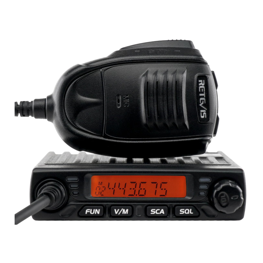
FUNCTIONS & FEATURES
RT98 Mobile Radio has nice housing, stoutness & stability, advanced and reliable functions, perfect & valuable. This amateur mobile radio especially designs for drivers and it pursues company philosophy of innovation and practicality.
More functions as follows:
- There are Amateur operation mode and Professional operation mode for option.
- Adopt superior quality material, better technology and high quality radiator to ensure stable and durable operation.
- 199 programmable memorized channels, identified by editing name.
- Various scan functions including CTCSS/DCS Scan function.
- Automatic calling Identification function by CTCSS or DCS signaling.
- Different band width per channel, 25K for wide band, 12.5K for narrow band.
- Frequency Step 2.5K, 5K, 6.25K, 10K, 12.5K, 20K, 25K, 30K, 50K
ACCESSORIES
Standart Accessories

Radio

Install bracket

User Manual

non-slip mat

Adjusting screws

Screws

Pads

Fuse(5A 250V)

Microphone Hanger
Optional Accessories

PC Cable

Regulated Power

8 ohm Speaker

Programming Software

Car Antenna
INITIAL INSTALLATION
Mobile Installation
To install the transceiver, select a safe, convenient location inside your vehicle that minimizes danger to your passengers and yourself while the vehicle is in motion. Consider installing the unit at an appropriate position so that knees or legs will not strike it during sudden braking of your vehicle. Try to pick a well ventilated location that is shielded from direct sunlight.
- Install the mounting bracket in the vehicle using the supplied self- tapping screws (2pcs) and flat washers (2pcs).

- Position the transceiver, then insert and tighten the supplied hexagon SEMS screws. Double check that all screws are tightened to prevent vehicle vibration from loosening the bracket or transceiver.


Intall Microphone Hanger
- Choose idea location and mark for screw point.
![]()
- Fix the hanger by the srews in accessory list.
![]()


Power Connection
![]() » Locate the power input connector as close to the transceiver as possible.
» Locate the power input connector as close to the transceiver as possible.
Mobile Operation
The vehicle battery must have a nominal rating of 12V. Never connect the transceiver to a 24V battery. Be sure to use a 12V vehicle battery that has sufficient current capacity. If the current to the transceiver is insufficient, the display may darken during transmission, or transmitting output power may drop excessively.
- Route the DC power cable supplied with the transceiver directly to the vehicle's battery terminals using the shortest path from the transceiver.
- We recommend you do not use the cigarette lighter socket as some cigarette lighter sockets introduce an unacceptable voltage drop.
- The entire length of the cable must be dressed so it is isolated from heat, moisture, and the engine secondary (high voltage) ignition system/ cables.
- After installing cable, in order to avoid the risk of damp, please use heat-resistant tap to tie together with fuse box. Don't forget to reinforce whole cable.
- In order to avoid the risk of short circuit, please cut down connection with negative (-) of battery, then connect with radio.
- Confirm the correct polarity of the connections, then attach the power cable to the battery terminals; red connects to the positive (+) terminal and black connects to the negative (-) terminal.
- Use the full length of the cable without cutting off excess even if the cable is longer than required. In particular, never remove the fuse holders from the cable.
- Reconnect any wiring removed from the negative terminal.

- Connect the DC power cable to the transceiver's power supply connector.
- Press the connectors firmly together until the locking tab clicks.

- Press the connectors firmly together until the locking tab clicks.


Fixed Station Operation
In order to use this transceiver for fixed station operation, you will need a separate 13.8V DC power supply (not included), power supply( QRP-01) as optional accessories. Please contact local dealer to require.
The recommended current capacity of your power supply is 10A.
- Connect the DC power cable to the regulated DC power supply and ensure that the polarities are correct. (Red: positive, Black: negative).
- Do not directly connect the transceiver to an AC outlet.
- Use the supplied DC power cable to connect the transceiver to a regulated power supply.
- Do not substitute a cable with smaller gauge wires.

- Connect the transceiver's DC power connector to the connector on the DC power cable.

![]()
» Press the connectors firmly together until the locking tab clicks.
» Before connecting the DC power to the transceiver, be sure to switch the transceiver and the DC power supply OFF.
» Do not plug the DC power supply into an AC outlet until you make all connections.
Fuse Replacement
This radio adopt 5A, 250V fuse.
If the fuse blows, determine the cause, then correct the problem. After the problem is resolved, replace the fuse. If newly installed fuses continue to blow, disconnect the power cable and contact your authorized Retevis dealer or an authorized Retevis servicecenter for assistance.
- Open the fuse holder

- Replace the fuse and screw on the holder.


| Fuse Location | Fuse Current Rating |
| Transceiver | 5A |
| Supplied Accessory DC power cable | 5A |
Only use fuses of the specified type and rating, otherwise the transceiver could be damaged.
![]()
» If you use the transceiver for a long period when the vehicle battery is not fully charged, or when the engine is OFF, the battery may become discharged, and will not have sufficient reserves to start the vehicle. Avoid using the transceiver in these conditions.
Antenna Connection
Before operating, install an efficient, well-tuned antenna. The success of your installation will depend largely on the type of antenna and its correct installation. The transceiver can give excellent results if the antenna system and its installation are given careful attention.
Use a 50Ω impedance antenna and low-loss coaxial feed-line that has a characteristic impedance of 50Ω, to match the transceiver input impedance. Coupling the antenna to the transceiver via feedlines having an impedance other than 50Ω reduces the efficiency of the antenna system and can cause interference to nearby broadcast television receivers, radio receivers, and other electronic equipment.
![]()
» Transmitting without first connecting an antenna or other matched load may damage the transceiver. Always connect the antenna to the transceiver before transmitting.
» All fixed stations should be equipped with a lightning arrester to reduce the risk of fire, electric shock, and transceiver damage.

The possible locations of antenna on a car are shown as following
Accessories Connections
External Speaker
If you plan to use an external speaker, choose a speaker with an impedance of 8Ω. The external speaker jack accepts a 3.5mm (1/8") mono (2-conductor) plug.

![]()
» External speaker adopt double port BTL, please care about the connecting way. The speaker can not connect with the ground, otherwise the speaker will be fault. The wrong connecting way as the following picture.

PC Connecting

To utilize the optional RT98 software, you must first connect the transceiver to your PC then using an optional programming cable. Please use RT98 software for programming. http://www.retevis.com
![]()
» Ask your dealer about purchasing a Programming Cable.
GETTING ACQUAINTED
Front Panel

Basic Function
| NO. | Knob | Function |
| 1 | FUN | Function Menu key |
| 2 | V/M | VFO/Memory mode switch key |
| 3 | SCA | Scan key |
| 4 | SQL | Squelch key |
| 5 | VOL | Power on/off and volume key |
| 6 | RX indicator | Light on when squelch valide |
| 7 | TX indicator | Light on when TX |
| 8 | LCD display | Display channel / frequency / function setting |
| 9 | Speaker | Listen to calls |
Press Fun key until F icon appears then press following key
| NO. | Knob | Function |
| 1 | V/M | Channel store |
| 2 | SCA | Channel scan delete or add |
| 3 | SQL | CTCSS/DCS setting |
| 4 | VOL | Keypad lock |
Hold Fun key then press following key
| NO. | Knob | Function |
| 1 | V/M | Delete memory channel |
| 2 | SQL | Voltage display function |
Keep press following key
| NO. | Knob | Function |
| 1 | FUN | Enter setting mode after hold it for 2 seconds |
| 2 | SQL | Turn monitor |
Rear Panel

Basic Function
| NO. | Knob | Function |
| 1 | Antenna connector | Connect a 50Ω antenna |
| 2 | External Speaker jack | Connect optional SP01 external speaker |
| 3 | Power cable | Connect a standard DC power cable |
Display

- F: Display when press FUN key
- CT: Display when setting CTCSS
- T: Display when setting TX CTCSS
- DCS: Display when setting DCS
- +: Display when setting positive offset direction
- -: Display when setting negative offset direction
- R: Display when turn on reverse frequency function
- N: Display when setting narrow band
![]() : Display when setting keypad lock function
: Display when setting keypad lock function- H: Display when setting high power
- M: Display when setting middle power
- L: Display when setting low power
- 188: Display memory channel number in memory mode
- Decimal point: Display when store channel indicate empty channel
- Decimal point: Display this icon when setting channel scan skip
- Decimal point: Indicates the decimal point of frequency and the scanning function
- Decimal point: Display this icon when setting CTCSS/DCS scan
- 888888: Indicate frequency or memory channel name
- 25/5/75: Display this icon when indicates the end of the frequency.
- BUSY: Display when receive the signal or turn on the monitor function
- RSSI: Display TX/RX signal strength

WORKING MODE AND MENU FUNCTION
According to practical application, you can set the radio works as Amateur Transceiver mode or Professional Transceiver mode. There are also 2 levels operation menu to set functions as you need. It is easy and convenient (From No.1 to No. 10 are channel function setup, From No.11 to No.20 are general setting setup).
Working Mode
- By programming software: In PC software's "General Setting" menu, choose "Display Mode" to select Amateur Transceiver mode or Professional Transceiver mode.
- By manual setup: Please refer to "Display Mode" .
Amateur Transceiver Mode
Except setting as "CH" mode, others considered as Amateur transceiver mode. Under this mode, press [V/M] key to switch between Channel mode and VFO mode.
- Frequency + Channel mode: When set display as "FR", it enters into Frequency+ Channel mode. Under this mode, new setting of channel operation and shortcut operation can be temporarily used by user. Once the radio is turned off or switched to another channel, the temporary setting will be erased and back to initial settings. If the program software's channel store is valid, the Shortcut operation and channel setting will be changed & stored as the latest value permanently. Once the radio is turned off or changed to new VFO frequency, the latest setting is remained until next change.
- Channel+ Name Tag Mode: When set display as "NM", it enters into Channel +Name Tag mode. At this mode, it will display corresponding channel name when the current channel is edited with name. Otherwise, it will display frequency + channel. Its operations are the same as frequency + channel mode.
- VFO Mode(Frequency mode): Under this mode, the Shortcut operation and channel setting will be changed & stored as the latest value permanently. Once the radio is turned off or changed to new VFO frequency, the latest setting is remained until next change.
Professional Transceiver Mode
When set display mode as "CH", it enters into Professional Transceiver mode. At this mode, except scan, other shortcut operation can't operate. And from No.1-10 menu in function setting will be auto hidden. They should be set by PC software. If there is corresponding name for current channel, the LCD will display current channel name Otherwise, it shows current channel number.
![]()
» If transceiver programmed as professional transceiver mode and locked, you can't return to amateur transceiver mode by manual operation from general setting.
Under Every Mode
From No. 11-20 menu in general setting can be changed and saved.
BASIC OPERATION
Switching the Power On/Off
When the transceiver in power off, press [VOL] key to power on or base on function menu APO set as power on once connect the power, then hold [VOL] key for 2 seconds to power off.
Power Voltage Display Function
After the transceiver connect the power cable, press [FUN] key and [SQL] key same time for 1 second can confirm current power voltage, then you can see the voltage data from the LCD display. The LCD display voltage will change once the power voltage has changed.
![]()
» The display voltage range is from 9V to 17V, the display data is a rough data, if you need exactly data pls use the voltmeter to test.
Adjusting the Volume
When the transceiver in power on, turn VOL knob, the LCD display VOL-XX, XX means volume level, can increase or decrease the volume, turn clockwise VOL knob can increase the volume, turn anticlockwise VOL knob to decrease volume. When set the volume as 1st level, then the transceiver in mute status.
Switch Between VFO and Channel Mode
In standby, press V/M until LCD appears M. this indicates the radio is in channel mode. Repeate above operation to switch between frequency mode(VFO) and channel mode.
Adjusting Frequency/Channel
- In frequency mode, Short press [UP] or [DN] key to increase or decrease frequency. Hold [UP] or [DN] to fast increase or decrease frequency. Short press [VOL], the MHz will flash, hold [UP] or [DN] key will change the frequency move by 1 MHz. Press [VOL] key again, the MHZ will flash, hold [UP]/[DN] key will change the frequency move by 10MHZ, press any key exit this mode.
![]()
» 2.5K, 5K, 6.25K, 10K, 12.5K, 20K, 25K, 30K and 50K total nine step size available for this radio.
- In channel mode, short press [UP] or [DN] key to increase or reduce channel by one step. Hold [UP] or [DN] key to fast increase or reduce channel.
Receiving
When the channel you are operating being called, the screen shows BUSY icon and field strength. The green RX indicator light on, in this way you can hear the calling.
![]()
» If the transceiver has set at higher squelch level, it may fail to hear the calling.
If the transceiver LCD display BUSY icon and field strength, the green LED Rx indicator flashes, but can not hear the calling, it means has receive matching carrier but with unmatching signaling (Pls reference CTCSS/DCS encode and decode for operation).
Transmitting
Hold [SQL] key to monitor for a while, to confirm the current channel is not busy, then release [SQL] key and back to standby state. Hold [PTT] key and speaker into microphone. Hold the microphone approximately 2.5-5.0cm from your lips and speak into the microphone in your normal speaking voice to get best timbre.
![]()
» Hold PTT key, the LED lights red and power strength show in the screen, indicates it is transmittin g, release PTT to receive.
Channel Edit
- In VFO mode, press [UP]/[DN] or [VOL] to choose wanted frequency.
- Press [FUN] key+ [SQL] to enter CTCSS/DCS setup. Press [UP]/[DN] or [VOL] to select desired signaling.
- Enter channel menu No 1-10 and choose related setup.
- Press [FUN] key, the LCD displays F icon, if the channel number flash means current channel number is valid. If M icon flashes means current channel number is empty.
- Press [UP]/[DN] key or turn VOL knob choose wanted channel number.
- Press [V/M] key store the channel, the decimal point icon disappear, the channel number no flash and emit a prompt, it means the channel stored success.
Channel Delete
- In channel mode, press [UP] / [DN] to choose a unwanted channel.
- Hold [FUN] and [V/M] key for over 1 second, the current channel will be deleted, the radio emit a prompt and jump to next working channel.
SHORTCUT OPERATION
Squelch Off / Squelch Off Momentary
SQL key programmed as Squelch Off or Squelch Off Momentary to monitor the weak signal.
- Squelch Off: Press [SQL] key to disable squelch, press [SQL] key again to resume squelch.
- Squelch Off Momentary: Press [SQL] key to disable squelch, release key to resume squelch.
![]()
» The above functions should be set in program software.
Squelch Level Setup
This function use for setting RX signal strength, the calling will be heard only when reach set level, otherwise the radio will keep mute.
- In standby, hold [SQL] key, then short press [UP]/[DN] or turn VOL Knob, the LCD displays current squelch level.
- Press [UP]/[DN] or turn VOL knob to choose wanted squelch level.
- Press any key to confirm and exit.
Frequency Scan
In frequency (VFO) mode, this function is designed to monitor signal of all frequency points under each step size.
- In VFO mode, short press [SCA] to start frequency scan.
- Short press [UP] or [DN] to change scan direction.
- Short press [UP]/[DN] key or any other key except the volume knob to exit scan.
Channel Scan
In channel mode, this function is used to monitor signal in all channels.
- In channel mode, Press [SCA] key start channel scan.
- Short press [UP]/[DN] key to change scan direction.
- Short press [UP]/[DN] key or any other key except the volume knob to exit scan.
Scan Skip
In channel mode, separately short press [FUN] key and [SCA] key to add or delete a scan channel. 1. Decimal point between frequency's ten digit and unit digit disappears, the current channel added to scan list. this channel will be scanned when scan function start.
2. Decimal point display between frequency's ten digit and unit digit, the current channel is deleted from scan list, this channel will not be scanned when start scan function.
CTCSS/DCS Encode and Decode Setup
Separately short press [FUN] key and [SQL] key to enter CTCSS/ DCS encode/decode menu, repeatedly short press [SQL], to set CTCSS/DCS encode/decode for current channel.
- When the LCD displays T, means current channel set with CTCSS encode, press [UP]/[DN] key or turn VOL knob to choose wanted encode.
- When the LCD displays CT, means current channel set with CTCSS encode/decode, press [UP]/[DN] key or turn VOL knob to choose wanted CTCSS decode.
- When the LCD displays DCS, means current channel set with DCS encode/decode, press UP/DN key or turn VOL knob to choose wanted DCS encode/decode.
- CTCSS code: 62.5-254.1 total 51 groups. DCS code: 000N-777I total 1024 groups, N is positive code, I is inverse code. Press V/M to choose positive code or inverse code.
- Press [UP]/[DN] key or any other key except volume knob to exit.
![]()
» Under channel mode, this operation can be temporarily used by user. Once the radio is turned off or switched to another channel, the temporary setting will be erased. If the channel setting programmed for valid, the temporary setting will keep valid until next change, turn off radio or switch to another channel, the temporary setting will not changed.
CTCSS Scan
Separately short press [FUN] key and [SOL] key to enter CTCSS/ DCS encode/decode menu, repeatedly short press [SQL] key until LCD displays CT, short press [SCA] key can enter CTCSS scan mode. Short press [UP] or [DN] key can change the scan direction, Once finding a matching CTCSS signaling, it will stop for 5S then scan again. Press any key to exit.
DCS Scan
Separately short press [FUN] key and [SQL] key to enter CTCSS/ DCS encode/decode menu, repeatedly short press [SQL] key until LCD displays DCS, short press [SCA] key to enter DCS scan mode. Short press [UP] or [DN] key can change the scan direction. Once finding a matching DCS signaling, it will stop for 5S then scan again. Press any key to exit.
Keypad Lockout
Avoiding unintentional operation, this function will lock the keys except [PTT] key and [FUN] key.
- Short press [FUN] key the LCD displays F icon, press [VOL] key again the LCD displays Lock means the keypad is locked.
- Repeate above operation, when Lock icon disappears, means the keypad is unlocked.
Function Menu
- Hold [FUN] key for over 2S to enter function menu.
- Short press [UP]/[DN] or turn VOL knob to switch menu option.
- Short press [VOL] key to enter 2nd level menu setup
- Short press [UP]/[DN] key or turn VOL knob to choose current setting.
![]()
» There are 2 part of function menu: part 1, Menu No. 1-10 channel function menu. part 2 Menu No. 11-20 function menu. Part 1 will automatically hide in channel mode by program software.
Signaling Combination Setup
Enter No. 01 function menu, the LCD displays "SKP". This function can improve the level of blocking irrelative signals.
SQ: You can hear the calling when receive a matching carrier.
CTC: You can hear the calling when receive a matching carrier and CTCSS/DCS signaling.
Default: SQ
![]()
» This setting is valid only when CTCSS/DCS signaling added.
HIGH/MID/LOW Power Selection
Enter No. 02 function menu, the LCD displays "POW". This function use to control transmit power level.
HI: Transmit with high power.
MI: Transmit with middle power.
LO: Transmit with low power.
Default: HI.
Band-width Selection
Enter No 03 function menu, the LCD displays "BNAD".
Select suitable bandwidth in accordance with different local conditions
WIDE: band width is 25k(Wide band)
NAR: band width is 12.5k(Middle band)
Default: WIDE.
Busy Channel Lockout
Enter No 04. function menu, the LCD displays "BUSY".
BCLO is to disable transmitting while RX signal is received. Once the channel is busy and you press [PTT], the radio will beep as warning and get back to receiving.
BU: Enable BCLO, Carrier lockout, transmitting is inhibited when current channel receives a matching carrier; press [PTT] to emit error voice prompt and back to receiving mode.
RL: Enable BTLO, transmitting is inhibited when current channel receives a matching carrier but dis-matching CTCSS/DCS. Press [PTT] key to emit error voice prompt and back to receiving mode.
OFF: BCLO is disabled. It can transmit in any receiving status.
Default: OFF.
Editing Channel Name
Enter No.05 function menu, the LCD displays "NAME".
- Press [UP]/[DN] or turn VOL knob to choose character for present cursor location.
- Press [V/M] key to confirm and move to next character edit.
- Press [FUN] key to return to last character edit.
![]()
» In Frequency (VFO) mode, this function will be auto-hidden.
TX OFF
Enter No.06 function menu, the LCD displays: "TX".
This function use to disable the transmitting for current channel.
ON: TX allowed, press [PTT] to transmit.
OFF: TX not allowed, press [PTT] will emit a wrong report.
Default: ON.
Reverse Frequency
Enter No.07 function menu, the LCD display "REV".
When turn on this function, the TX frequency turns to RX frequency & RX frequency changes to TX frequency. The signaling will reverse if CTCSS/DCS signaling existed in this channel.
ON: Turn on reverse function
OFF: Turn off reverse function
Default: OFF.
Talk Around
Enter No.08 function menu, the LCD displays "TALK".
This function enable direct communication with other radios in case the repeater is not activated or when out of the repeater range. The transceiver will transmit by RX frequency with its CTCSS/DCS signaling.
ON: Turn on talk around function
OFF: Turn off talk around function
Default: OFF.
Offset Direction Setup
Enter NO.09 function menu, the LCD display "SHIFT".
Repeater receives a signal(UP-LINK) on one frequency and retransmits on another frequency
(DOWN-LINK). The difference between these two frequencies is called the offset frequency. If the UP-LINK frequency is higher than DOWN-LINK frequency, the direction is positive, If it is lower, the shift direction is negative.
+: It indicates positive offset, which means transmitting frequency higher than receiving frequency.
-: It indicates negative offset, which means transmitting frequency lower than receiving frequency.
OFF: Turn off offset direction function
Default: OFF.
Offset Frequency Setup
Enter NO.10 function menu, the LCD displays "OFFSET".
0-90: Total 90MHZ frequency range available
Default: 5.0MHz
![]()
» The offset frequency change base on the frequency step setting.
Frequency Step Size Setup
Enter No.11 function menu, the LCD displays "STEP".
This function is valid only in frequency (VFO) mode, input frequency or frequency scanning are restricted by frequency step size.
Total 9 frequency step size available: 2.5K, 5K, 6.25K, 10K, 12.5K, 20K, 25K, 30K and 50K.
Default: 25K
![]()
» This function is auto-hidden in memory mode.
Display Mode Setup
Enter No.12 function menu, the LCD displays "DSP".
This radio has 3 different dispaly modes:
FRQ: Frequency+Channel mode ( Amateur transceiver mode)
CH: Channel mode
NM: Channel+Name Tag mode (Amateur transceiver mode), if channel not named ( Amateur transceiver mode), it displays Frequency+Channel mode. Default: FRQ.
![]()
» This function will be auto-hidden if channel mode locked.(Refer to programming software).
BEEP Prompt Setup
Enter No.13 function menu, the LCD displays "BEEP".
The prompt function is confirm the transceiver's operation, it will emit BEEP prompt sound when with wrong operation.
ON: Turn on BEEP prompt function
OFF: Turn off BEEP prompt function
Default: ON.
TOT(Time Out Timer)
Enter No.14 function menu, the LCD displays "TOT".
The time-out timer limits continuous transmitting time. When transmit time exceed programmed value, the transmitting will stop and emit a prompt. 1-30: 1-30 minutes range available by 1 minute/step
OFF: Turn off TOT function.
Default level: 03.
APO Setup
Enter No.15 function menu, the LCD displays "APO".
Once APO is activated, the radio will be automatically switched off when the preset timer is running to end.
30: Auto power off after 30m
60: Auto power off after 1h
120: Auto power off after 2h
OFF: Disable Auto power off
Default: OFF.
Squelch Level Setup
Enter No.16 function menu, the LCD displays "SQL".
This function use for setting RX signal strength, the calling will be heard only when reach set level, otherwise the radio will keep mute.
OFF-09: Total 10 levels, OFF is lowest value(Open)
Default: 03
![]()
» If the transceiver has set at higher squelch level, it may fail to hear the calling. If set at lower squelch level, the radio will be interfered.
Scan Dwell Time Setup
Enter No.17 function menu, the LCD displays "SCAN".
This radio has 3 kinds of Scan Dwell Time way.
SE: It stops once scanning a matching signal.
TO: It pauses 5s once scanning a matching signal, then resume scan.
CO: It pauses once scanning a matching signal, signal disappeared then resume scan.
Default: TO.
Power On Method Setup
Enter NO.18 function menu, the LCD displays "AOP".
After turn off this function, the transceiver will be power on only by manually pressing VOL key.
ON: Auto-power on
OFF: Power on by manual
Default: ON.
Mic Gain Setup
Enter No.19 function menu, the LCD displays "MIG".
1-16: total 16 levels for optional
Default: 6
Reset Factory Default
Enter No.20 function menu, the LCD displays "RESET".
If your radio seems to be malfunctioning, resetting the microprocessor may solve the problem.
FACT: All channel, signaling function setup resume factory default.
SETUP: No.10-20 function menu setup resume factory default.
PROGRAMMING SOFTWARE INSTALLING AND STARTING (IN WINDOWS XP SYSTEM)
- Double click "RT98-Setup.exe", then follow the installing instruction.
- Click start menu in computer, under "ALL PROGRAMS" menu, choose and click "USB To Com port" in RT98 program, install "USB To Com port" driver by indication.
- Connect the optional USB Programming cable to USB port in PC with transceiver.
- Double click RT98 shortcut or click RT98 inprocedure index of start menu, choose serial com port as indicated then click OK to start programming software.
- According to instruction, select correct "COM Port, then click "OK" to start programming software.
![]()
» Even in same computer, the selective COM Port is different when USB cable connects with different USB port.
You shall install software before connecting the USB cable line. Switch on transceiver before writing frequency. You had better not switch on or off the power supply of transceiver when it is connected with computer, otherwise, it will make transceiver unable to read or write frequency. In this case, you have to turn off programming software, pull out USB cable. then reinsert USB cable and open software, then rechoose COM Port, it will turn into normal operation. Therefore, please connect transceiver with computer after switching on the transceiver. Don't restart transceiver power when it is connected with computer.
MAINTENANCE
Default Setting after Resetting
| RT98 | ||
| Frequency | VHF | UHF |
| VFO Frequency | 145.000MHz | 435.000MHz |
| Memory CH 1-199 | CH1: 145.000MHz | CH1: 435.000MHz |
| Offset Direction | -- | -- |
| Offset Frequency | 600KHz | 5MHz |
| Channel Step | 12.5KHz | 25KHz |
| CTCSS Encode/Decode | -- | -- |
| CTCSS Frequency | 88.5Hz | 88.5Hz |
| DCS Encode/Decode | -- | -- |
| DCS Code | 023N | 023N |
| Power Output | HI | HI |
| TOT | 3 | 3 |
| Squelch Level | 3 | 3 |
| Volume | 28 | 28 |
Default Setting after Resetting
| NO. | Problem | Possible Causes and Potential Solutions |
| 1 | Power is on, nothing appears on Display | + and - polarities of power connection are reversed. Connect red lead to plus terminal and black lead to minus terminal of DC power supply. |
| 2 | Fuse is blown | Check and solve problem resulting in blown fuse and replace fuse with new fuse. |
| 3 | No sound comes from speaker. |
|
| 4 | Key and Dial do not function | Key-lock function is activated. Cancel Key-lock function |
| 5 | No Scan | Did not list the channel in the scan when programmed. |
| 6 | The whole band with noise after programmed | The squelch has opened during programmed |
| 7 | Communication range was short, bad sensitivity |
|
| 8 | Can not talk with other members within the group |
|
SPECIFICATIONS
| GENERAL | |
| Frequency Range | VHF:136-174MHz; UHF:400-490MHz |
| Number of Channels | 199 channels |
| Channel Spacing | 25KHz(Wide Band); 12.5KHz(Narrow Band) |
| Phase-locked Step | 2.5K,5K,6.25K,10K,12.5K,20K,25K,30K,50K |
| Operating Voltage | 13.8V DC ±15% |
| Squelch | Carrier/CTCSS/DCS |
| Frequency Stability | ±2.5ppm |
| Operating Temperature | -20~+60C |
| TRANSMITTER | ||
| Wide Band | Narrow Band | |
| Sensitivity (12dB SINAD) | ≤0.25μV | ≤0.35μV |
| Adjacent Channel Selectivity | ≥60dB | ≥60dB |
| Intermodulation | ≥60dB | ≥60dB |
| Spurious response | ≥60dB | ≥60dB |
| Audio Response | +1~-3dB(0.3~3KHz) | +1~-3dB(0.3~3KHz) |
| Hum & Noise | ≥45dB | ≥40dB |
| Audio Distortion | ≤5% | |
| Audio Power Output | >2W@16R | |
| Transmitting | ||
| Wide Band | Narrow Band | |
| Power Output | 15W / 10W / 5W | |
| Modulation | 16KΦF3E | 11KΦF3E |
| Adjacent Channel Power | ≥70dB | ≥60dB |
| Hum & Noise | ≥40dB | ≥36dB |
| Spurious Emission | ≥60dB | ≥60dB |
| Audio Response | +1~-3dB(0.3~3KHz) | +1~-3dB(0.3~3KHz) |
| Audio Distortion | ≤5% | |
51 groups CTCSS Tone Frequency(Hz)
| No. | Freq.(Hz) | No. | Freq.(Hz) | No. | Freq.(Hz) | No. | Freq.(Hz) |
| 1 | 62.5 | 14 | 100.0 | 27 | 156.7 | 40 | 196.6 |
| 2 | 67.0 | 15 | 103.5 | 28 | 159.8 | 41 | 199.5 |
| 3 | 69.3 | 16 | 107.2 | 29 | 162.2 | 42 | 203.5 |
| 4 | 71.9 | 17 | 110.9 | 30 | 165.5 | 43 | 206.5 |
| 5 | 74.4 | 18 | 114.8 | 31 | 167.9 | 44 | 210.7 |
| 6 | 77.0 | 19 | 118.8 | 32 | 171.3 | 45 | 218.1 |
| 7 | 79.7 | 20 | 123.0 | 33 | 173.8 | 46 | 225.7 |
| 8 | 82.5 | 21 | 127.3 | 34 | 177.3 | 47 | 229.1 |
| 9 | 85.4 | 22 | 131.8 | 35 | 179.9 | 48 | 233.6 |
| 10 | 88.5 | 23 | 136.5 | 36 | 183.5 | 49 | 241.8 |
| 11 | 91.5 | 24 | 141.3 | 37 | 196.2 | 50 | 250.3 |
| 12 | 94.8 | 25 | 146.2 | 38 | 189.9 | 51 | 254.1 |
| 13 | 97.4 | 26 | 151.4 | 39 | 192.8 |
1024 groups DCS Code
| 000 | 001 | 002 | 003 | 004 | 005 | 006 | 007 |
| 010 | 011 | 012 | 013 | 014 | 015 | 016 | 017 |
| 020 | 021 | 022 | 023 | 024 | 025 | 026 | 027 |
| 030 | 031 | 032 | 033 | 034 | 035 | 036 | 037 |
| 040 | 041 | 042 | 043 | 044 | 045 | 046 | 047 |
| 050 | 051 | 052 | 053 | 054 | 055 | 056 | 057 |
| 060 | 061 | 062 | 063 | 064 | 065 | 066 | 067 |
| 070 | 071 | 072 | 073 | 074 | 075 | 076 | 077 |
| 100 | 101 | 102 | 103 | 104 | 105 | 106 | 107 |
| 110 | 111 | 112 | 113 | 114 | 115 | 116 | 117 |
| 120 | 121 | 122 | 123 | 124 | 125 | 126 | 127 |
| 130 | 131 | 132 | 133 | 134 | 135 | 136 | 137 |
| 140 | 141 | 142 | 143 | 144 | 145 | 146 | 147 |
| 150 | 151 | 152 | 153 | 154 | 155 | 156 | 157 |
| 160 | 161 | 162 | 163 | 164 | 165 | 166 | 167 |
| 170 | 171 | 172 | 173 | 174 | 175 | 176 | 177 |
| 200 | 201 | 202 | 203 | 204 | 205 | 206 | 207 |
| 210 | 211 | 212 | 213 | 214 | 215 | 216 | 217 |
| 220 | 221 | 222 | 223 | 224 | 225 | 226 | 227 |
| 230 | 231 | 232 | 233 | 234 | 235 | 236 | 237 |
| 240 | 241 | 242 | 243 | 244 | 245 | 246 | 247 |
| 250 | 251 | 252 | 253 | 254 | 255 | 256 | 257 |
| 260 | 261 | 262 | 263 | 264 | 265 | 266 | 267 |
| 270 | 271 | 272 | 273 | 274 | 275 | 276 | 277 |
| 300 | 301 | 302 | 303 | 304 | 305 | 306 | 307 |
| 310 | 311 | 312 | 313 | 314 | 315 | 316 | 317 |
| 320 | 321 | 322 | 323 | 324 | 325 | 326 | 327 |
| 330 | 331 | 332 | 333 | 334 | 335 | 336 | 337 |
| 340 | 341 | 342 | 343 | 344 | 345 | 346 | 347 |
| 350 | 351 | 352 | 353 | 354 | 355 | 356 | 357 |
| 360 | 361 | 362 | 363 | 364 | 365 | 366 | 367 |
| 370 | 371 | 372 | 373 | 374 | 375 | 376 | 377 |
| 400 | 401 | 402 | 403 | 404 | 405 | 406 | 407 |
| 410 | 411 | 412 | 413 | 414 | 415 | 416 | 417 |
| 420 | 421 | 422 | 423 | 424 | 425 | 426 | 427 |
| 430 | 431 | 432 | 433 | 434 | 435 | 436 | 437 |
| 440 | 441 | 442 | 443 | 444 | 445 | 446 | 447 |
| 450 | 451 | 452 | 453 | 454 | 455 | 456 | 457 |
| 460 | 461 | 462 | 463 | 464 | 465 | 466 | 467 |
| 470 | 471 | 472 | 473 | 474 | 475 | 476 | 477 |
| 500 | 501 | 502 | 503 | 504 | 505 | 506 | 507 |
| 510 | 511 | 512 | 513 | 514 | 515 | 516 | 517 |
| 520 | 521 | 522 | 523 | 524 | 525 | 526 | 527 |
| 530 | 531 | 532 | 533 | 534 | 535 | 536 | 537 |
| 540 | 541 | 542 | 543 | 544 | 545 | 546 | 547 |
| 550 | 551 | 552 | 553 | 554 | 555 | 556 | 557 |
| 560 | 561 | 562 | 563 | 564 | 565 | 566 | 567 |
| 570 | 571 | 572 | 573 | 574 | 575 | 576 | 577 |
| 600 | 601 | 602 | 603 | 604 | 605 | 606 | 607 |
| 610 | 611 | 612 | 613 | 614 | 615 | 616 | 617 |
| 620 | 621 | 622 | 623 | 624 | 625 | 626 | 627 |
| 630 | 631 | 632 | 633 | 634 | 635 | 636 | 637 |
| 640 | 641 | 642 | 643 | 644 | 645 | 646 | 647 |
| 650 | 651 | 652 | 653 | 654 | 655 | 656 | 657 |
| 660 | 661 | 662 | 663 | 664 | 665 | 666 | 667 |
| 670 | 671 | 672 | 673 | 674 | 675 | 676 | 677 |
| 700 | 701 | 702 | 703 | 704 | 705 | 706 | 707 |
| 710 | 711 | 712 | 713 | 714 | 715 | 716 | 717 |
| 720 | 721 | 722 | 723 | 724 | 725 | 726 | 727 |
| 730 | 731 | 732 | 733 | 734 | 735 | 736 | 737 |
| 740 | 741 | 742 | 743 | 744 | 745 | 746 | 747 |
| 750 | 751 | 752 | 753 | 754 | 755 | 756 | 757 |
| 760 | 761 | 762 | 763 | 764 | 765 | 766 | 767 |
| 770 | 771 | 772 | 773 | 774 | 775 | 776 | 777 |

Documents / Resources
References
Download manual
Here you can download full pdf version of manual, it may contain additional safety instructions, warranty information, FCC rules, etc.
Advertisement


Need help?
Do you have a question about the RT98 and is the answer not in the manual?
Questions and answers