Vertiv Liebert PST5, PST5-350MT120, PST5-500MT120 - UPS Manual
- Installer/user manual (28 pages) ,
- Quick installation manual (2 pages)
Advertisement
PST5 DESCRIPTION
The Liebert® PST5 is an off-line/stand-by UPS designed with the features you need providing reliable power protection for small home/office computers, network gear, and home-entertainment equipment. Designed with controls for user-friendly operation, the Liebert® PST5 provides the run time to save work in process.
Available Models
Table 1.1 PST5 Models
| MODEL NUMBER | NOMINAL POWER RATING |
| PST5-350MT120 | 350 VA/200 W |
| PST5-500MT120 | 500 VA/300 W |
| PST5-660MT120 | 660 VA/400 W |
| PST5-850MT120 | 850 VA/500 W |
Controls and Features
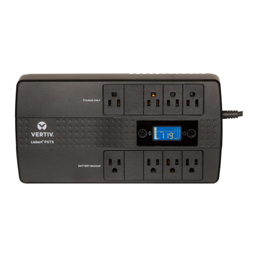
Figure 1.1 PST5-350MT120 and PST5-500MT120 Controls and Features

| ITEM | DESCRIPTION |
| 1 | Surge-protected-only output-power receptacles |
| 2 | Red Fault LED |
| 3 | Power button |
| 4 | Green Mode LED |
| 5 | Battery-backed and surge-protected output power receptacles |
| 6 | Input Power Cord |
| 7 | Input Circuit Breaker |
| 8 | RJ11/45 connectors for phone/fax/modem or network surge protection. |
| 9 | USB Type B connector for USB communication with a PC for UPS monitoring and PC shut-down. |
Figure 1.2 PST5-660MT120 and PST5-850MT120 Controls and Features

| ITEM | DESCRIPTION |
| 1 | Surge-protected-only output-power receptacles |
| 2 | Scroll button |
| 3 | Power button |
| 4 | LCD Display with icons and numerical information |
| 5 | Battery-backed and surge-protected output power receptacles |
| 6 | Input Power Cord |
| 7 | Input Circuit Breaker |
| 8 | USB charging port (5 V, 2.0 A) |
| 9 | Coax Cable connections for cable modem, DSS receiver, or cable-TV converter surge-protection connection. |
| 10 | RJ11/45 connectors for phone/fax/modem or network surge-protection connection. |
| 11 | USB Type B connector for USB communication with a PC for UPS monitoring and PC shut-down. |
INSTALLATION
What's Included
- USB cable; one 2 m (6.5 ft) long
- Coax cable; one 1 m (3 ft) long (PST5-660MT120 and PST5-850MT120 models only)
- Quick Installation Guide
- Safety and Regulatory Guidelines
- Wall-mounting template
Unpacking and Inspection
Unpack the UPS and conduct the following checks:
- Inspect the UPS for shipping damage. If any shipping damage is found, report it to the carrier and your local dealer or your Vertiv representative immediately.
- Check the accessories included in packaging list. If there is any discrepancy, contact your local dealer or your Vertiv representative immediately.
Preparation for Installation
Installation Environment
- Install the UPS indoors in a controlled environment, where it cannot be accidentally turned Off. The installation environment should meet the specifications listed in Specifications.
- Place it in an area of unrestricted air-flow around the unit, away from water, flammable liquids, gases, corrosives, and conductive contaminants. Avoid direct sunlight.
- The socket outlet should be nearby and easily accessible.
- This UPS is not for use in a computer room as defined in the standard for the Protection of Electronic Computer/Data Processing Equipment ANSI/NFPA 75.
 NOTE: Operating the UPS in temperatures above 77°F (25°C) reduces battery life.
Installation Clearances
Maintain at least 4 in (100 mm) clearance in the front and rear. Do not obstruct the air inlets on the front panel and rear panel. Blocking the air inlets reduces ventilation and heat dissipation, shortening the service life of the UPS.
Installing the UPS
Connecting Loads
The UPS has 4 battery-backed outlets and surge-protected receptacles and 4 surge-protected-only receptacles. Plug your critical equipment (such as computer, monitors, etc.) into the battery-backed receptacles and your less-critical equipment (such as printers and other less-often used peripherals) into the surge-only receptacles. Take note not to exceed the output-load rating of the UPS.
Connecting for Network or TelephoneProtection
Protection from electrical surges to your computer network or telephone is provided. Use the network/telephone surge-protection ports on the rear panel. Connect the "IN" port to the line from the wall jack and the "OUT" port to your device port. Use of this feature is not required for proper operation of the UPS.
Connecting for Television/Cable Protection
NOTE: For PST5-660MT120 and PST5-850MT120 models only.
Surge protection for your cable modem, DSS Receiver, or cable-TV connection is also provided using the coax surge-protection ports on the rear panel. Connect the "IN" port to the line from the wall jack and the "OUT" port to your device port. Use of this feature is not required for proper operation of the UPS.
USB Communication Connection
You can connect the PST5 to a computer via USB allowing unattended, controlled-shutdown of your computer in case of UPS input power failure. The UPS works with the computer running software built-in within the Microsoft® Windows® operating system. Use of this feature is not required for proper operation of the UPS. To use this feature, plug the provided USB cable into USB Type-B port located on the side panel of the UPS and the other end into an open USB port on your computer.
USB Charging Ports
NOTE: For PST5-660MT120 and PST5-850MT120 models only.
The PST5 has an easily-accessible, side-panel USB Type-A charging port. This port charges phones or other small USB powered devices. The port provides up to 2.0 A of charge current. You may plug devices into this port at any time during installation and operation.
Connecting AC Input
Ensure that all the loads are first powered off. Connect to an input-power supply/wall outlet that is properly protected by a circuit breaker in accordance with national and local electrical codes. The input receptacle must be grounded. See Specifications for input cord rating.
Once the UPS is plugged into the wall outlet, it begins charging the battery.
NOTE: While every precaution has been taken to ensure that the battery is in good condition, we recommend allowing the UPS to be plugged into AC input and to charge the battery for at least 12 hours prior to providing full back-up time protection for any utility-power abnormality.
OPERATION
Modes of Operation
NOTE: In all of the following modes, including Off mode:
The UPS always provides surge protection and input-breaker protection to the 4 battery backed-up outlets and the 4 surge-only outlets. The UPS does not need to be On to provide this protection. The surge-only outlets always have the same voltage level as the UPS input voltage, even when the UPS is Off. The surge-only outlets are not voltage regulated, battery backed-up, or switched by the UPS.
Off Mode
The UPS input is plugged into a stable, 120-VAC source, but the battery-backed-up outlets are turned off. The internal batteries are charging.
NOTE: The surge-only outlets will still have power.
On/Normal Mode
The UPS input is plugged into a stable, 120-VAC source, and the battery-backed-up outlets are turned on. The internal batteries are charging.
On/Battery Mode
The UPS input is not plugged in, or the voltage source has become extremely low or high and unusable. The UPS automatically switches to the internal battery to provide normal, usable voltage to the batterybacked-up outlets.
NOTE: The surge-only outlets will not have power.
Fault Mode
An error or fault condition has occurred. The battery-backed-up outlets are shut off and the internal batteries are not charging.
NOTE: The surge-only outlets may still have power if the UPS input is plugged in.
Battery Self-test Mode
The UPS enters a cycle of approximately 10 seconds during which it tests the internal battery. The battery-backed-up outlets are still temporarily powered by the internal battery. Self-test mode occurs at the following instances:
- At start-up turning the UPS On.
- Automatically every 8 weeks as a self-check.
- Manually by pressing and holding the power button for 3 seconds when the unit is On.
Controls
Figure 3.1 Buttons on PST5-350MT120 AND PST5-500MT120 Models

Table 3.1 Button Controls
| ITEM | DESCRIPTION |
| 1 | Power button.
|
Figure 3.2 Buttons on PST5-660MT120 AND PST5-850MT120 Models

Table 3.2 Button Controls
| ITEM | DESCRIPTION |
| 1 | Scroll button.
|
| 2 | Power button.
|
Display-panel Indicators
NOTE: The display automatically powers-off to conserve power. However, the display remains on when there is a warning or fault to call attention to the event.
Figure 3.3 LED indicators on PST5-350MT120 AND PST5-500MT120 Models

Table 3.3 Front-panel Indicators
| ITEM | DESCRIPTION |
| 1 | Warning/Fault, red LED. See Warnings, and Faults, for descriptions and troubleshooting. |
| 2 | On/AC/Battery, green LED
|
Figure 3.4 LCD Display on PST5-660MT120 AND PST5-850MT120 Models

Table 3.4 Display Icons and Indicators
| ITEM | DESCRIPTION |
| 1 | Battery mode when lit. |
| 2 | Battery-mode alarm muted when lit. See Audible-tone Indicators on the facing page, for more details |
| 3 | Normal mode when lit. |
| 4 | Output-overload warning when flashing. See Warnings on the facing page, for more details |
| 5 | Output-load level graph in 25% increments |
| 6 | Numeric display of UPS operational parameters:
|
| 7 | Fault when lit. Fault codes indicated:
See Faults for more details |
| 8 | Battery-capacity graph in 25% increments |
Audible-tone Indicators
Table 3.5 Tones and Beeps of the UPS
| TYPE | INDICATES |
| 1 beep every 10 seconds | Battery mode |
| 2 beeps every second | UPS warning |
| 2 beeps every 5 seconds | Low-battery warning |
| 3 beeps every 30 seconds | Replace-battery warning |
| Constant, solid tone | UPS fault |
| 3-second tone followed by 2 beeps | Power-on in battery self-test mode |
| 1 long tone | Power off |
| 3 beeps | Manual battery self-test |
Warnings
The UPS has two early-warning indicators that allow the UPS to function normally for a short period before the outputs are shut-off.
Table 3.6 Warning Indicators and Actions for PST5-350MT120 AND PST5-500MT120 Models
| RED LED | AUDIBLE TONE | DESCRIPTION | SUGGESTED TROUBLESHOOTING |
| On solid | 1 beep every second | The load devices plugged-in to the UPS output are drawing more power than the UPS rating. | Reduce the load to below the UPS rating in the specifications table, see Specifications |
| Blinking | 2 beeps every 5 seconds or 3 beeps every | The battery is weak or damaged. | Charge the UPS battery for at least 12 hours, or replace the battery, see Battery Replacement. |
Table 3.7 Warning Indicators and Actions for PST5-660MT120 AND PST5-850MT120 Models
| ICON DISPLAYED | AUDIBLE TONE | DESCRIPTION | SUGGESTED TROUBLESHOOTING |
 | 1 beep every second | Output-overload. The load devices plugged-in to the UPS output are drawing more power than the UPS rating. | Reduce the load to below the UPS rating in the specifications table, see Specifications. |
 | 3 beeps every 30 seconds | The battery is weak or damaged. | Charge the UPS battery for at least 12 hours, or replace the battery, see Battery Replacement. |
Faults
The PST5-350MT120 AND PST5-500MT120 Models fault indicator is the red LED on the front panel. If this Warning/Fault LED is on solid, and there is a continuous audible tone, the UPS has detected a problem and automatically shut off the output.
To troubleshoot the fault:
Turn-off the UPS, disconnect all loads, and restart the UPS.
- If the fault is still active, contact Vertiv technical support for a replacement.
- If the fault is no longer active, plug in equipment one at a time to locate the device that is causing the fault.
PST5-660MT120 AND PST5-850MT120 Models display fault codes, described in Fault Codes and Actions for PST5-660MT120 AND PST5-850MT120 Models below, when it detects a problem and automatically shuts-off output power.
Table 3.8 Fault Codes and Actions for PST5-660MT120 AND PST5-850MT120 Models
| FAULT CODE | DESCRIPTION | SUGGESTED TROUBLESHOOTING |
| E01 | Output short circuit. | Turn-off the UPS, disconnect all loads, and restart the UPS.
|
| E04 | Output over-voltage during battery mode. | Turn-off the UPS, disconnect all loads, and restart the UPS.
|
| E05 | Battery-charge failure. | Turn-off the UPS and call Vertiv technical support for a replacement unit. |
| E06 | Internal battery is dead or damaged. | Charge the UPS for at least 12 hours or replace the battery, see Battery Replacement. |
Normal Start-up
- With the UPS connected to AC input, press-and-hold the power button for 1 second. A long tone and 2 short beeps sound while the UPS is in battery self-test mode for a few seconds. After a successful self-test, the outlets are on.
Normal Shut-down
- Press-and-hold the power button for 1 second. The outlets are turned off.
- Disconnect AC-input power.
- Remove the battery cover and disconnect the battery connector.
Full Shut-down
- Press-and-hold the power button for 1 second. The outlets are turned off.
- Disconnect AC-input power.
- Remove the battery cover and disconnect the battery connector. The unit is fully shut down.
MAINTENANCE AND BATTERY REPLACEMENT
Precautions
Although the PST5 is designed and manufactured to ensure personal safety, improper use can result in electrical shock or fire. To ensure safety, observe the following precautions:
- Turn off and unplug the UPS before cleaning it.
- Clean the UPS with a dry cloth. Do not use liquid or aerosol cleaners.
- Never block or insert any objects into the ventilation holes or other openings of the UPS.
- Do not place the UPS power cord where it might be damaged.
Battery Charging
The batteries are valve-regulated, non-spill-able, lead acid and should be kept charged to attain their design life. The PST5 charges the batteries continuously when it is connected to the utility input power. If the PST5 will be stored for a long time, we recommend connecting the UPS to input power for at least 24 hours every 4 to 6 months to ensure full recharge of the batteries.
Battery Replacement

Before you proceed, please review the battery safety precautions available at https://www.vertivco.com/ComplianceRegulatoryInfo.
You may safely replace the internal battery pack. See the in Specifications, for the part number of the replacement battery for your UPS model number.
To replace the battery:
- Power-off the UPS and disconnect the input power.
- Turn the UPS upside down.
- Remove the battery-compartment screw, then slide off the battery-compartment cover, see Removing the cover and battery.
- Lift the white tab and pull the battery out, see Removing the cover and battery.
Figure 4.1 Removing the cover and battery

- Disconnect the red battery connector, then the black battery connector.
- Orient the replacement battery in the same way as the removed battery, connect the black battery connector, then the red battery connector.
NOTE: When connecting the last wire to the battery, there can be a small spark. This is normal.
- Seat the battery fully into the UPS and replace the compartment cover and screw.
- Press-and-hold the power button for 3 seconds to initiate the battery self-test and clear any previous battery fault warning.
- Properly dispose of the old batteries at an appropriate recycling facility or return them to Vertiv in the packing material for the new batteries.
Specifications
Table 5.1 PST5 Specifications
| MODEL NUMBER | PST5-350MT120 | PST5-500MT120 | PST5-660MT120 | PST5-850MT120 |
| Capacity (VA / W) | 350 / 200 | 500 / 300 | 660 / 400 | 850 / 500 |
| Unit Dimensions, in. (mm) W x D x H | 12 x 6.24 x 3.82 (305 x 158.5 x 97) | |||
| Unit Weight, lbs (kg) | 6.6 (3.0) | 7.7 (3.5) | 9.4 (4.3) | 9.7 (4.4) |
| Shipping Dimensions, in. (mm) W x D x H | 15 x 10.5 x 8 (381 x 266.7 x 203.3) | |||
| Shipping Weight, lbs (kg) | 7.9 (3.6) | 9.0 (4.1) | 10.6 (4.8) | 11.0 (5.0) |
| Input AC | ||||
| Nominal Voltage | 120 VAC | |||
| Voltage Range | 90-145 VAC | |||
| Input Voltage Measurement Tolerance | ±5% | |||
| High Line Normal Mode to Battery Mode | 145 VAC | |||
| High Line Battery Mode to Normal Mode | 140 VAC | |||
| Low Line Battery Mode to Normal Mode | 95 VAC | |||
| Low Line Normal Mode to Battery Mode | 90 VAC | |||
| Frequency Range | 60 Hz, ±5 Hz | |||
| Internal Rear-panel Input Breaker Rating | 5 A, 250 VAC | 7 A, 250 VAC | 10 A, 250 VAC | |
| Surge Energy Rating | 316 Joules | |||
| Input Cord | 6 ft. attached with NEMA 5-15P | |||
| Output AC (On Utility) | ||||
| Nominal Voltage | 120 VAC | |||
| Voltage Range | 90-145 VAC | |||
| Frequency Range | 60 Hz, ±5 Hz | |||
| Efficiency | >95% at full load | |||
| Output AC (On Battery) | ||||
| Nominal Voltage | 120 VAC | |||
| Voltage Range | Nominal ±8% at onset, ±15% at EOD | |||
| Frequency Range | 60 Hz, ±1 Hz | |||
| Waveform | PWM Simulated Sine wave | |||
| Transfer Time | 6-8 ms, typical | 6 ms, typical | ||
| Overload Capacity in Normal Mode | 100% - alarm warning 110% - alarm warning and shutdown after 5 minutes 120% - alarm warning and immediate shutdown | |||
| Overload Capacity in Battery Mode | 110% - alarm warning and shutdown after 5 seconds 120% - alarm warning and immediate shutdown | |||
| Protection | Electronic (over current, short circuit w/ latching shutdown) | |||
| Battery Type | Valve Regulated Lead Acid (VRLA) | |||
| Battery Manufacturer / Model | CSB / GP1245 Leoch / DJW12-4.5 | CSB / HR1221 Leoch / DJW12-5.0 | Leoch / DJW12-6.0 BB / BP5-12 | Leoch / DJW12-6.0 BB / SHR7-12 |
| Battery Quantity x VDC x Ah | 1 x 12V x 4.5Ah | 1 x 12V x 5.0Ah | 1 x 12V x 5.0/6.0Ah | 1 x 12V x 6.0/7.0Ah |
| Battery Backed Outlets | (4) NEMA 5-15R | |||
| Surge Only Outlets | (4) NEMA 5-15R | |||
| Environmental Requirements | ||||
| Operating Temperature, deg(degC) | 32-104 (0-40) | |||
| Operating Elevation, feet (meter) | 0-9,842 (0-3,000) | |||
| Relative Humidity | 0-95% non-condensing | |||
| Storage Temperature, degF (degC) | 5 to 113 (–15 to 45) | |||
| Storage Elevation, feet (meter) | 0-49,212 (0-15,000) | |||
| Audible Noise | <40 dBA @ 3 ft (1 m) from all sides | |||
| Agency | ||||
| Safety | cTUVus (UL 1778, 5th Edition; CSA 22.2 No. 107.3:2014) | |||
| RFI / EMI | FCC part 15 subpart B, CLASS B | |||
| Surge Immunity | EN61000-4-5, Level 2 (Line-Neutral) EN61000-4-5, Level 3 (Line-Ground) | |||
| Transportation | ISTA Procedure 1A | |||
Run-time Tables
Table 5.2 PST5-120 Battery Run Times
| MODEL RATING | ||||
| LOAD PERCENT OFCAPACITY | 350 VA/200 W | 500 VA/300 W | 660 VA/400 W | 850 VA/500 W |
| 10% | 86 | 60 | 56 | 50 |
| 20% | 46 | 29 | 28 | 22 |
| 25% | 32 | 22 | 13 | 16 |
| 30% | 26 | 19 | 14 | 13 |
| 40% | 19 | 12 | 11 | 9 |
| 50% | 11 | 9 | 7.5 | 6.5 |
| 60% | 10 | 7 | 6.5 | 5 |
| 70% | 8 | 5.5 | 5 | 4 |
| 75% | 7.2 | 5.2 | 4.2 | 3.2 |
| 80% | 7 | 5 | 4 | 3 |
| 90% | 5 | 3.5 | 3 | 2 |
| 100% | 4 | 3 | 2 | 1.5 |
| Note: Run times in this table are approximate. They are based upon new, fully charged standard battery modules at a temperature of 25 degC (77 degF) with 100% resistive UPS loading. | ||||
IMPORTANT SAFETY INFORMATION
This manual contains important safety instructions that must be followed during the installation and maintenance of the UPS and batteries. Read this manual thoroughly and the safety and regulatory information, available at https://www.vertivco.com/ComplianceRegulatoryInfo, before attempting to install, connect to supply, or operate this UPS.
Technical Support
If you encounter any installation or operational issues with your product, check the pertinent section of this manual to see if the issue can be resolved by following outlined procedures. Visit https://www.VertivCo.com/en-us/support/ for additional assistance.
Our Technical Support staff is ready to assist you with any installation or operating issues you may encounter with your Liebert® product. Please call or e-mail us:
Technical support:
e: liebert.upstech@vertivco.com
p: 1-800-222-5877 menu option 1
Monitoring support:
e: liebert.monitoring@vertivco.com
p: 1-800-222-5877 menu option 2
Warranty support:
e: microups.warranty@vertivco.com
p: 1-800-222-5877 menu option 3
Documents / Resources
References
Download manual
Here you can download full pdf version of manual, it may contain additional safety instructions, warranty information, FCC rules, etc.
Download Vertiv Liebert PST5, PST5-350MT120, PST5-500MT120 - UPS Manual
Advertisement


Need help?
Do you have a question about the Liebert PST5 and is the answer not in the manual?
Questions and answers