Vertiv Liebert PSI5 Series Installer And User Manual
Hide thumbs
Also See for Liebert PSI5 Series:
- Installer/user manual (52 pages) ,
- Quick installation user's manual (8 pages) ,
- Quick installation user's manual (8 pages)

Related Manuals for Vertiv Liebert PSI5 Series


Summary of Contents for Vertiv Liebert PSI5 Series
- Page 1 Liebert® PSI5 120V Input/120V Output & 208V Input/208V Output Installer/User Guide...
- Page 2 The products covered by this instruction manual are manufactured and/or sold by Vertiv. This document is the property of Vertiv and contains confidential and proprietary information owned by Vertiv. Any copying, use or disclosure of it without the written permission of Vertiv is strictly prohibited.
-
Page 3: Table Of Contents
3.1.7 Battery Self-Test Mode 3.1.8 Controls 3.2 Display Panel Indicators 3.3 Audible-Tone Indicators 3.4 Warnings 3.5 Faults 3.6 Normal Startup 3.7 Normal Shutdown 3.8 Full Shutdown 3.9 Configuring UPS with the Settings Menu Vertiv | Liebert® PSI5 Installer/User Guide |... - Page 4 4 Maintenance and Battery Replacement 4.1 Precautions 4.2 Battery Charging 4.3 Replacing the UPS Batteries 5 Specifications 5.1 Run Times Vertiv | Liebert® PSI5 Installer/User Guide |...
-
Page 5: Important Safety Information
IMPORTANT! This manual contains important safety instructions that must be followed during the installation and maintenance of the UPS and batteries. Read this manual thoroughly and the safety and regulatory information, available at https://www.vertiv.com/ComplianceRegulatoryInfo, before attempting to install, connect to supply, or operate this UPS. - Page 6 This page intentionally left blank Vertiv™ | Liebert® PSI5 Installer/User Guide...
-
Page 7: Psi5 Description
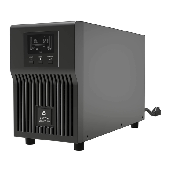
1 PSI5 DESCRIPTION The Liebert®PSI5 is a line-interactive UPS designed for IT applications such as network closets and small data centers. It is available in 1U, 2U, MT (mini tower) and and LI (lithium-ion) form factors. It provides reliable power protection for servers, critical nodes, network workstations, large network peripherals, network routers, bridges, hubs and other electronic equipment. -
Page 8: Rear Panel Views
Table 1.2 PSI5-800/1100/1500RT120 Rear Panel Descriptions ITEM DESCRIPTION Grounding Screw Network/Fax/Modem Surge Protection Input/Output External Battery Connector USB Port Programmable Receptacles Non-Programmable Receptacles SNMP IntelliSlot Port Emergency Power Off (EPO) Connector Input Circuit Breaker AC Input Vertiv™ | Liebert® PSI5 Installer/User Guide... - Page 9 Figure 1.2 Liebert® PSI5-2200RT120 Rear Panel Table 1.3 PSI5-2200RT120 Rear Panel Descriptions ITEM DESCRIPTION Grounding Screw Network/Fax/Modem Surge Protection Input/Output External Battery Connector USB Port Programmable Receptacles Non-Programmable Receptacles SNMP IntelliSlot Port Emergency Power Off (EPO) Connector Input Circuit Breaker AC Input 1 PSI5 Description...
- Page 10 Table 1.4 PSI5-3000RT120 Rear Panel Descriptions ITEM DESCRIPTION Grounding Screw Network/Fax/Modem Surge Protection Input/Output External Battery Connector USB Port Programmable Receptacles Non-Programmable Receptacles SNMP IntelliSlot Port Emergency Power Off (EPO) Connector Input Circuit Breaker AC Input Output Circuit Breaker Vertiv™ | Liebert® PSI5 Installer/User Guide...
- Page 11 Figure 1.4 Liebert® PSI5-5000RT208 Rear Panel Table 1.5 PSI5-5000RT208 Rear Panel Descriptions ITEM DESCRIPTION Grounding Screw Network/Fax/Modem Surge Protection Input/Output External Battery Connector USB Port Programmable Receptacles Non-Programmable Receptacles SNMP IntelliSlot Port Emergency Power Off (EPO) Connector Input Circuit Breaker AC Input 1 PSI5 Description...
- Page 12 Figure 1.5 PSI5-1000/1500RM1201U Rear Panel Table 1.6 Liebert® PSI5-1000/1500RM1201U Rear Panel Descriptions ITEM DESCRIPTION Liebert® IntelliSlot Port Input Circuit Breaker AC Input Emergency Power Off (EPO) Connector USB Port Programmable Receptacles Non-Programmable Receptacles Vertiv™ | Liebert® PSI5 Installer/User Guide...
- Page 13 Figure 1.6 Liebert® PSI5 Mini Tower Rear Panels Table 1.7 Mini Tower Rear Panel Descriptions ITEM DESCRIPTION PSI5-750/1100MT120 PSI5-1500MT120 Network/Phone/DSL Surge-Protection Connectors Grounding Screw Liebert® IntelliSlot Port Non-Programmable Receptacles Programmable Receptacles AC Input USB Port AC Input Breaker Emergency Power Off (EPO) Connector 1 PSI5 Description...
- Page 14 Figure 1.7 Liebert PSI5-1500RT120LI Rear Panel ITEM DESCRIPTION AC Input Network/Fax/Modem Surge Protection Input/Output External Battery Connector USB Port SNMP IntelliSlot™ Port Programmable Receptacles Non-Programmable Receptacles Emergency Power Off (EPO) Connector Input Circuit Breaker Grounding Screw Vertiv™ | Liebert® PSI5 Installer/User Guide...
- Page 15 Figure 1.8 Liebert PSI5-3000RT120LI Rear Panel ITEM DESCRIPTION AC Input External Battery Connector Network/Fax/Modem Surge Protection Input/Output SNMP IntelliSlot™ Port USB Port Programmable Receptacles Non-Programmable Receptacles Output Circuit Breakers Emergency Power Off (EPO) Connector Input Circuit Breaker Grounding Screw 1 PSI5 Description...
-
Page 16: Front Panel
Figure 1.9 Controls and Display on 2U, MT and LI Models ITEM DESCRIPTION ON/MUTE button. See Controls on page 24, for details. SELECT button. See Controls on page 24, for details. OFF/ENTER button. See Controls on page 24, for details. Vertiv™ | Liebert® PSI5 Installer/User Guide... - Page 17 Figure 1.10 Controls and Display on 1U Models ITEM DESCRIPTION ON/MUTE button. See Controls on page 24, for details. SELECT button. See Controls on page 24, for details. OFF/ENTER button. See Controls on page 24, for details. 1 PSI5 Description...
- Page 18 This page intentionally left blank Vertiv™ | Liebert® PSI5 Installer/User Guide...
-
Page 19: Installation
• Inspect the UPS for shipping damage. If any shipping damage is found, report it to the carrier and your local dealer or your Vertiv™ representative immediately. • Check the accessories included in the packing list. If there is any discrepancy, contact your local dealer or your Vertiv representative immediately. -
Page 20: Installing The Ups
Rotate the display by pulling out, and turning it clockwise until it is seated in the proper orientation. Connect the two halves of the stand together. Place the UPS in the stands. Make sure that the stands are installed 70 mm (2.76 in.) from the edge of the unit. Vertiv™ | Liebert® PSI5 Installer/User Guide... - Page 21 Figure 2.2 Attaching stands to the UPS and external battery ITEM DESCRIPTION Connect the two halves of the stand to the spacer, after installing the additional stand components shown in item 4, and install the securing screws. Place the UPS and external battery pack in the stands. (Rotate the display on the UPS if needed, see Figure 2.1 on the previous page.) Make sure that the stands are installed 70 mm (2.76 in.) from the edge of the unit.
- Page 22 Install the UPS in the rack. Figure 2.4 Installing the external battery in a rack ITEM DESCRIPTION Attach the brackets to the external battery. Install the supplied rack kit into the rack. Install the external battery in the rack. Vertiv™ | Liebert® PSI5 Installer/User Guide...
-
Page 23: Installing A 1U Model
2.4.2 Installing a 1U Model CAUTION: Do not use the mounting brackets to lift the unit. Use the mounting brackets only to secure the UPS to the rack. See Figure 2.5 below to install the unit. Figure 2.5 Installing the UPS in a rack ITEM DESCRIPTION Attach the brackets to the UPS. -
Page 24: Usb Connection
NOTE: After installation and initial startup, set the number of installed battery cabinets in the UPS Settings. NOTE: When two or more external battery cabinets are used with PSI5-1100/2200/3000/5000 models, the UPS load rating is decreased by 20%. Vertiv™ | Liebert® PSI5 Installer/User Guide... -
Page 25: Network Communication Card Connection (Optional)
Remove the two screws and protective cover on the Network Communications Port on the rear panel. 2. Insert the card into the port and secure it with the screws. 3. Refer to the documentation with the card or at www.Vertiv.com for cable connection and operation. 2.10.1 Connecting AC Input... - Page 26 NOTE: While every precaution has been taken to ensure that the battery is in good condition, Vertiv™ recommends plugging the UPS into AC input and to charge the battery for at least 12 hours prior to providing full backup time protection for any utility power abnormality.
-
Page 27: Operation
3 OPERATION 3.1 Modes of Operation 3.1.1 Off Mode The UPS input is plugged into a stable, nominal source, but the outlets are turned Off. The internal batteries are charging. 3.1.2 On/Normal Mode The UPS input is plugged into a stable, nominal source, and the outlets are turned On. The internal batteries are charging. 3.1.3 On/Automatic Voltage Regulation (AVR)/Boost Mode The UPS input is plugged in, but the voltage source is abnormally low (brown-out). -
Page 28: Controls
3.1.8 Controls Figure 3.1 Display and Buttons on the front panel of 2U and MT units Figure 3.2 Display and Buttons on the front panel of 1U units Vertiv™ | Liebert® PSI5 Installer/User Guide... - Page 29 Table 3.1 Control button descriptions ITEM DESCRIPTION On/Mute Button. Powers the UPS On and other functions depending on the current operating mode. • UPS On: When in Off mode, press and hold for 2 seconds to enter Battery Self-Test mode, then On mode. •...
-
Page 30: Display Panel Indicators
Estimated backup time in H (hours), M (minutes), or S (seconds) Indicates warning and fault codes. See Faults on page 29, and Warnings page 28. Displays various UPS operation parameters. Settings menu. See Configuring UPS with the Settings Menu on page 30. Audible On/Battery mode alarm silenced Vertiv™ | Liebert® PSI5 Installer/User Guide... -
Page 31: Audible-Tone Indicators
Table 3.2 Display icons, sections and functions (continued) ICONS AND DISPLAY DESCRIPTION UPS output load in 25% increments Battery level in 25% increments Low battery Overload icon Programmable outlet icon Battery icon Battery charging icon 3.3 Audible-Tone Indicators Table 3.3 Tones and Beeps of the UPS TYPE INDICATES ... -
Page 32: Warnings
Replacing the UPS Batteries on page 33. connected Over charge Call Vertiv customer support, 1-800-222-5877. Remove the EPO state on the EPO connector. Emergency Power Off activated NOTE: Output immediately shuts Off when the EPO warning occurs. Vertiv™ | Liebert® PSI5 Installer/User Guide... -
Page 33: Faults
Inverter voltage high Turn Off the UPS, disconnect all connected loads and restart the UPS. If the fault is still active, call Vertiv customer Inverter support, 1-800-222-5877. If the fault is no longer active, plug each piece of equipment in one at a time to locate the device voltage low that has the short circuit. -
Page 34: Configuring Ups With The Settings Menu
4. Use the up/down arrow buttons to select the setting, then press OFF/Enter. See Table 3.6 on the facing page, for the settings. 5. When finished, select program option 00, and press OFF/Enter to exit Settings mode. Vertiv™ | Liebert® PSI5 Installer/User Guide... - Page 35 Table 3.6 Settings Menu Options PROGRAM SETTING OPTIONS NUMBER Nominal voltage setting. Set the nominal system voltage to match the input voltage of the UPS. This setting affects the buck/boost/on- battery transfer points and sets the output voltage in Battery mode. For 120VAC models: •...
- Page 36 This page intentionally left blank Vertiv™ | Liebert® PSI5 Installer/User Guide...
-
Page 37: Maintenance And Battery Replacement
In all cases, the batteries should be kept charged to retain their design life. The PSI5 charges the batteries continuously when it is connected to input power. If the PSI5 will be stored for a long time, Vertiv™recommends connecting the UPS to input power every 4 to 6 months for at least 2 hours for LI models and 24 hours for lead acid models to ensure full recharge of the batteries. - Page 38 10. Press and hold the power button for 3 seconds to initiate the Battery-Self Check mode clearing any previous battery fault warning. 11. Properly dispose of the old batteries at an appropriate recycling facility or return them to Vertiv™ in the packing material from the new batteries.
- Page 39 5. Press and hold the power button for 3 seconds to initiate the Battery-Self Check mode clearing any previous battery fault warning. 6. Properly dispose of the old batteries at an appropriate recycling facility or return them to Vertiv™ in the packing material from the new batteries.
- Page 40 Slide out the battery kit and disconnect the battery connector. Connect the battery connector to the replacement battery. Slide the replacement battery kit into the UPS. Replace the battery cover. Secure the battery cover with the screws. Vertiv™ | Liebert® PSI5 Installer/User Guide...
-
Page 41: Specifications
5 SPECIFICATIONS Table 5.1 on the next page, lists the specification for the Liebert® PSI5 2U UPS models. Table 5.2 on page 41, lists the specification for the PSI5 1U and MT UPS models. 5 Specifications... - Page 42 Vertiv | Liebert® PSI5 Installer/User Guide |...
- Page 43 Vertiv | Liebert® PSI5 Installer/User Guide |...
- Page 44 Vertiv | Liebert® PSI5 Installer/User Guide |...
- Page 45 Vertiv | Liebert® PSI5 Installer/User Guide |...
- Page 46 Vertiv | Liebert® PSI5 Installer/User Guide |...
- Page 47 Vertiv | Liebert® PSI5 Installer/User Guide |...
- Page 48 Vertiv | Liebert® PSI5 Installer/User Guide |...
- Page 49 Vertiv | Liebert® PSI5 Installer/User Guide |...
-
Page 50: Run Times
16.0 21.5 30.5 44.0 85.5 1034 1276 1519 Table 5.5 PSI5-1100RT120 NUMBER OF EBCS NUMBER OF EBCS LOAD LOAD INTERNAL BATTERY ONLY MINUTES MINUTES 1100 11.0 13.5 18.5 27.0 40.0 87.0 1003 1233 1463 Vertiv™ | Liebert® PSI5 Installer/User Guide... - Page 51 Table 5.6 Liebert® PSI5-1500RT120 NUMBER OF EXTERNAL BATTERY CABINETS LOAD INTERNAL BATTERY ONLY MINUTES 1500 1350 1350 1215 1200 1080 1050 11.0 14.0 18.0 24.0 34.0 50.0 110.5 1294 1594 1895 Table 5.7 PSI5-2200RT120 NUMBER OF EBCS NUMBER OF EBCS LOAD LOAD INTERNAL...
- Page 52 ONLY MINUTES MINUTES 4250 3825 4000 3600 3825 3443 3600 3240 3400 3060 3200 2880 2975 2678 2800 2520 2550 2295 2400 2160 2125 1913 2000 1800 1700 1530 1600 1440 1275 1178 1080 Vertiv™ | Liebert® PSI5 Installer/User Guide...
- Page 53 Table 5.10 PSI5-1000RM1201U LOAD MINUTES 1000 10.4 13.4 18.2 26.9 41.9 90.6 Table 5.11 PSI5-1500RM1201U LOAD MINUTES 1500 1350 1350 1215 1200 1080 1050 10.6 13.5 18.4 26.9 41.6 91.2 5 Specifications...
- Page 54 Table 5.12 PSI5-750MT120 LOAD MINUTES 607.5 472.5 10.9 13.8 337.5 17.7 23.5 202.5 33.0 48.0 67.5 92.5 Table 5.13 PSI5-1100MT120 LOAD MINUTES 1100 11.0 13.7 18.8 27.5 45.5 107.0 Vertiv™ | Liebert® PSI5 Installer/User Guide...
- Page 55 Table 5.14 PSI5-1500MT120 LOAD MINUTES 1500 1350 1350 1215 1200 1080 1050 11.2 14.1 18.1 24.2 34.2 50.4 110.9 Table 5.15 PSI5-1500RT120LI LOAD MINUTES 1500 1350 1350 1215 1200 1080 10.3 1050 12.1 14.6 17.7 22.8 30.6 45.3 89.0 5 Specifications...
- Page 56 Table 5.16 PSI5-3000RT120LI LOAD MINUTES 3000 2700 2700 2430 10.5 2400 2160 11.9 2100 1890 13.9 1800 1620 16.5 1500 1350 20.0 1200 1080 25.5 34.2 49.1 96.6 Vertiv™ | Liebert® PSI5 Installer/User Guide...
- Page 57 Vertiv™ | Liebert® PSI5 Installer/User Guide...
- Page 58 Vertiv.com | Vertiv Headquarters, 1050 Dearborn Drive, Columbus, OH, 43085, USA © 2020 Vertiv Group Corp. All rights reserved. Vertiv and the Vertiv logo are trademarks or registered trademarks of Vertiv Group Corp. All other names and logos referred to are trade names, trademarks or registered trademarks of their respective owners.
Need help?
Do you have a question about the Liebert PSI5 Series and is the answer not in the manual?
Questions and answers