Easee Home, Charge - Charging Station Manual
- User's installation manual (24 pages) ,
- Quick start manual (9 pages) ,
- Important product information (32 pages)
Advertisement
- 1 Introduction
- 2 Product overview
- 3 Technical specifications
- 4 Planning the installation
- 5 Charging Robot. Opening
- 6 Backplate. Mounting
- 7 Backplate. Preparing
- 8 Backplate. Wiring
- 9 Backplate. Installing
- 10 Chargeberry. Attaching
- 11 Front cover. Closing
- 12 Features
- 13 Charging Robot interface
- 14 Safety
- 15 Documents / Resources
Introduction
Read the Important product information guide in the product packaging before installing the product.
Installation and operation of the product requires a mobile device with internet connection.
Product overview
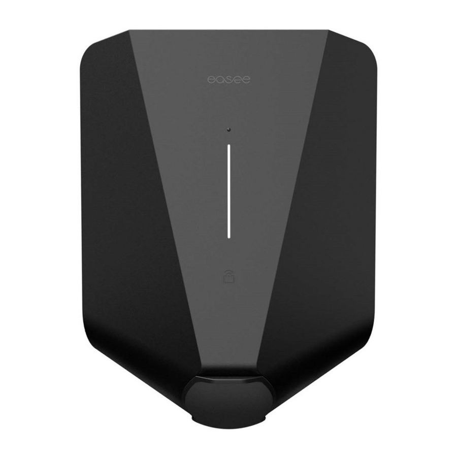
Front cover
Protects the electronics from external influences.

Chargeberry (22 kW)
Contains the electronics for charging the vehicle.

Backplate
For attaching and connecting to the charging infrastructure.

Installation kit

1 The blind plugs are pre-installed on the backplate.
Tool

Technical specifications
General
| Dimensions | 256 x 193 x 106 mm (H x W x D) |
| Wall mounting | c/c 160 x 125 mm (H x W) |
| Operating temperature | -30°C to +40°C |
| Weight | 1.5 kg |
Sensors and indicators
Light strip with LEDs showing the status of the charger
Touch button
Temperature sensors in all main contacts
Charging
| Charging power | 1.4–22 kW 6 A 1 phase – 32 A 3 phase (automatically adjusted in relation to available capacity) Up to 7.36 kW at 32 A 1 phase Up to 22 kW at 32 A 3 phase |
| Connection point | Type 2 socket (IEC 62196-2) |
| Number of phases | 1 or 3 (fully dynamic) |
| Voltage | 3x 230/400V AC (±10%) |
| Mains frequency | 50/60 Hz |
| Easee Home | Load balancing of up to 3 units per circuit |
| Easee Charge | Load balancing of up to 101 units per circuit |
| Built-in energy meter (±2%) | |
Connectivity
Built-in eSIM (LTE Cat M1/ 2G /GPRS)
WiFi 2.4 GHz b/g/n connection
Easee Link RF TM
Bluetooth BLE 4.2
Control charging via Easee App
RFID/NFC reader
OCPP 1.6 via our API
Protection
| Integrated overload protection according to EN IEC 61851-1:2019, 13.1. | |
| Integrated RCD type A 30 mA AC according to EN 60947-2, and 6 mA residual direct current detecting device (RDC-DD) complying with IEC 62955, 9.9. | |
| Rated conditional short-circuit current (I ) cc | 500 A (does not provide overcurrent protection according to EN 60947-2) |
| Degree of protection | IP54 (the backplate is IP22 without cover) |
| Impact resistance | IK10 |
| Insulation class | I |
| Pollution degree | 4 (installation environment) |
| EMC Classification | Class A & Class B |
| Overvoltage category | III |
Installation
| Installation network | TN, IT or TT (detected automatically) |
| Installation circuit breaker | Max 40 A (Easee Home) Max 80 A (Easee Charge) (Instantaneous trip, maximum 75 000 A²s) 2 |
| Wire material | Copper; solid, flexible, stranded |
| Wire cross-section | 2.5 to 16 mm 2 (single conductors)/ 2.5 to 10 mm 2 (parallel conductors, max 63 A through the backplate) PE cross-section must be equal to or larger than the phase wire cross-section Cable dimensions must adhere either to IEC 60364-5-52 or local regulations |
| Cable diameter | 8–22 mm |
| Terminal torque | 5 Nm |
| Cable strip length | 12 mm |
2 Complying with IEC 60947-2, IEC 60947-6-2 or IEC 61009-1 or with the relevant parts of the IEC 60898 series or the IEC 60269 series.
Planning the installation
Prior to the installation, it is recommended that you consider future charging needs, so that you can easily expand accordingly in the future.
If several Charging Robots are connected to the same circuit, the total current is dynamically distributed between them. The connected Charging Robots communicate wirelessly between each other, ensuring the circuit is not overloaded. The maximum charging current is set during configuration.
For an optimal result
- We always recommend a 3-phase installation if possible, to make it future-proof.
- If possible, use the largest approved cable crosssection (see Technical specifications).
- Consider the installation of Easee Ready backplates if the acquisition of further Charging Robots is planned for the future.
- To avoid overloading the building's main fuse, the Easee Equalizer can be used for dynamic load balancing. The maximum current value can also be set as required during configuration.
Special notes
- Several backplates can be connected in parallel, with a maximum load of 63 A through the terminals.
- Parallel conductors require twin ferrules when wired.
- The maximum supported charging current for the installation is only configurable by the installer. It cannot be altered by the user.
- If the charging infrastructure includes more than one Charging Robot, the backplate that is configured first becomes the master of its circuit.
- If more than 2 units are installed, the master unit should be located in the middle of the installation (if possible) for an optimal Easee Link communication.
- Site Key: During installation, a Site Key must be used to assign the Charging Robots to the correct location in the Easee Cloud. A Site Key will automatically be generated when creating a new charging site using the Easee Installer App or it can be obtained by creating a new charging site at portal.easee.com.
Your house, power grid and EV
The Charging Robot automatically adapts to the power grid, the electric car and the capacity of the electrical installation. In the table you can see what charging effect you can expect from your installation and situation. The table is only meant as a guide.

The type of installation as well as cable cross-sections must be determined by a qualified electrician in accordance with valid local, regional and national regulations for electrical systems.
| Load | Charging power | |
| Ampere (A) | 1 phase (kW) | 3 phase (kW)[1] |
| 6 | 1.4 | 4.1 |
| 8 | 1.8 | 5.5 |
| 10 | 2.3 | 6.9 |
| 13 | 3.0 | 9 |
| 16 | 3.7 | 11 |
| 20 | 4.6 | 13.8 |
| 25 | 5.8 | 17.3 |
| 32 | 7.4 | 22 |
Padlock
It's possible to lock the electronics with a padlock. This will create an extra layer of security (padlock is not included).
| Max total lock height | 56 mm |
| Shackle height (outer dimensions) | 19 - 20 mm |
| Shackle thickness | 3.2 - 4 mm |
3 Example for 400 V TN; deviating values for other grid types.
Residual Current Device (RCD)
- A Residual Current Device is integrated in the Charging Robot.
- The RCD will break the current in case a residual current exceeding 6mA DC or 30mA AC is detected.
- The RCD is automatically tested between each charging session or at least every 24h.
- For manual initialization of the RCD-test, please refer to the Installer App.
- The integrated RCD has no influence on the function of external protective devices.
- An external RCD is required when at least one of the below conditions are identified:
- The installation, including cable, junction boxes etc., includes components with only basic insulation (Class I).
- Any other electrical equipment apart from Easee Home or Easee Charge, including lamps and socket outlets, is connected to the circuit.
- Any other conditions identified by the authorized installer requiring an external RCD.
- The internal RCD is considered to provide the required RCD protection for both AC and DC leakage faults when all the below conditions are fulfilled:
- The installation, including cable, junction boxes etc, is performed entirely with components providing double or reinforced insulation (Class II).
- No other electrical equipment apart from Easee Home or Easee Charge, including lamps and socket outlets, is connected to the circuit.
- No other conditions identified by the authorized installer requiring an external RCD.
For more information about the RCD, please go to RCD Functional Description.

Turn off the power before you begin the installation. Use extreme caution and follow instructions carefully.
We recommend that you watch the installation videos available on our website: support.easee.com
Charging Robot. Opening

- Bend down the lower part of the rubber cover and insert the two ends of the supplied tool into the two openings at the bottom of the front cover.
- Pull the tool until the front cover comes loose and remove the cover.
- Grasp the Type 2 socket and push upwards with good force until the Chargeberry disconnects.
Backplate. Mounting

- Fix the backplate to a solid, non-perforated wall or structure with sufficient load-bearing capacity using the 4 wall screws provided in the mounting kit. Use suitable wall plugs for mounting and observe the local regulations for recommended installation height.
- The installation wall must cover the entire back of the product. If this is not possible to achieve, it is possible to use the Easee Mount.
- The area should not be exposed to direct rain, direct sunlight or explosive gases. A physical barrier is recommended to protect the charger.
- Install at a height of 130–140cm, with an angle no more than +/- 3 degrees from vertical. Suggested installation height for accessibility: 80–95 cm.
NOTE
If you are going to install multiple backplates, now would be a good time to mount them as well.
Backplate. Preparing

- Shorten the sealing plug to fit the cable. The hole should be slightly smaller to ensure a good seal.
- Insert the cable through one of the 4 cable entries and secure it to the backplate with the strain relief provided. There must be at least 5 mm of cable extending beyond the strain relief.
- Close all cable entries that are not in use with the blind sealing plugs supplied.
The wires must not cross over the screw terminals or the Chargeberry slots. This will prevent the Chargeberry from seating in the slots.
Backplate. Wiring

- Strip each wire, exposing 12 mm of copper on each. If the cable has flexible conductors, then you must use ferrules on stranded wires to make the connection. Use correct tools to press them.
- Tighten the screw terminal with a torque of 5 Nm.
NOTES
- When connecting multiple backplates in parallel, each screw terminal serves as a coupling point for adjacent backplates. All backplates must be connected with the same phase sequence. External junction boxes or flat cables can be used if it is more convenient.
- It's recommended to follow the existing colour codes used in the installation. Depending on national standards, the colours of the cables can vary from the illustrations. The illustrations in this manual follow the IEC 60446 standard.
- Before turning on the power, make sure the wires are properly connected and tightened. Test this by pulling on each wire.
- The PE must have an equal or larger cross-section than the phase wire.
TN/TT 3-phase (3x 230/400 V)

IT/TT 3-phase (3x 230 V)

TN 1-phase (230 V)

IT/TT 1-phase (230 V)

Backplate. Installing
- Scan the QR code to download the Easee Installer App and create a free account.
NOTE
Your phone needs to support Bl; uetooth or NFC. - Select one of the two site setups in the Installer App:
easee.com/installer-app
![]()

Create new site: If this is a completely new charging site, select "Create new site". Enter the installation details, follow the on-screen instructions and return to this guide afterwards.
Update existing site: If this site already has one or more Charging Robots installed or if it has been created by an operator (Easee Charge), select "Update existing site" and search for the site address. On "Site overview", select the circuit that you want the backplate to be part of and select "Add another backplate". Follow the on-screen instructions and return to this guide afterwards.
NOTE
If the charging circuits include more than one Charging Robot, the backplate that is configured first becomes the master unit of the charging infrastructure. To achieve the best communication flow, the centre backplate should be configured first.

Chargeberry. Attaching
Insulation testing should be performed before a Chargeberry is installed in the backplate. Testing the circuit insulation with the Chargeberry installed in the backplate may damage the electronics or impact the reading negatively.

- Turn on the power. The terminals of the backplates are now electrically live.
- Remove the PIN code sticker and attach it to the inside of the fuse cabinet, or another safe location for storage.
- Position the Chargeberry to fit into the slots on the backplate located in the center of the installation.
- When the Chargeberry is in the track, press it forcefully down until you hear a "CLICK".


NOTE
You do not need to touch the terminals of either the Chargeberry or the backplate when installing or removing the Chargeberry.
Front cover. Closing
Before closing the front cover, it is possible to lock the Chargeberry with a padlock (see Planning the installation).


- Hang the front cover at the top of the backplate and let it fall into place.
- Press the bottom of the front cover until you hear a click.
- Bend the lower part of the rubber cover down.
- Screw in the locking screw at the bottom of the charger to secure the front cover. NOTE! The locking screw is necessary to secure the cover and protect the charger from exposure.
- Close the rubber cover. If the cable is inserted from the bottom, you can cut a corresponding hole in the rubber cover to ensure a neat installation.
The charger is now ready for testing according to local regulations. Once complete, transfer ownership to the owner via the Installer App.
Features

- Touch button: The touch button is used to activate Bluetooth. Bluetooth connection in the app allows for local operation of the charger when no internet is available. Read more about the local interface at: easee.com/support/bt
- Light strip: The light strip communicates the status of the Charging Robot at all times. (See Charging Robot interface).
- RFID area: The integrated RFID reader enables access control of the Charging Robot and identification of different users. You can use it to unlock the charger with an Easee Key. Check our knowledge base at http://support.easee.com more details on how to add and manage your Easee Keys.
- Type 2 socket: The Type 2 socket is completely universal and allows you to charge any type of electric vehicle using the appropriate charging cable. Furthermore, it is possible to permanently lock the charging cable, so you do not have to worry about it being stolen.
NOTE: Adaptors should not be used on the charger or the charging cable. The charging cable must have appropriate sockets on each end.
Charging Robot interface
| Light description | Status |
| White – constant light, only at the bottom 2 LEDs – master unit / 1 LED – secondary units | Standby |
| White – constant light | Car connected |
| White – pulsating light | Charging in progress |
| Blue – constant light | Smart charging enabled (car connected) |
| Blue – pulsating light | Smart charging in progress |
| At startup, the LEDs turn on one by one. When the charger is updating, one or more LEDs will flash green while this is in progress. | Updating software (updating can take up to 30 minutes) NOTICE NOTICEThe car must be disconnected before a software update can be completed. |
| White – flashing light | Waiting for authentication by an RFID tag. Hold the RFID tag against the RFID area of the Charging Robot in order to authenticate and initiate the charging. |
| White – fast flashing light | RFID-tag received (awaiting key verification) |
| Red – flashing light, with warning sounds | Critical error! Turn off the power and remove the charging cable from the Charging Robot. The power can then be turned back on if necessary. The flashing red light will continue, but the warning sound will stop when the charging cable is disconnected. The charger is blocked from further use, cannot be reset and has to be replaced. Contact customer support. |
| Red – flashing light | Critical error! The charger is blocked from further use, cannot be reset and has to be replaced. Contact customer support. |
| Red – constant light | General error. Unplug the charging cable and replug it to the Charging Robot. If the red light persists, check the Easee App or our knowledge base 4 for further information. |
| Red – constant light, with warning sounds | Wires are connected incorrectly. Consult an authorised electrician. |
| Red – pulsating light | The Charging Robot has measured an abnormal temperature and has entered in safe mode. Please go to our knowledge base further information. |
| White – flashing light, only at the bottom | The Charging Robot is searching for its master unit. Please check the status of the master unit. For further information, please check our knowledge base 4. |
| Yellow – flashing light, only at the bottom | The Charging Robot is waiting to be configured. Consult an authorised electrician. |
4 Easee public knowledge base can be found at support.easee.com.
Safety
WARNINGS AND CAUTIONS
A Warning indicates a condition, hazard or unsafe practice that can result in serious personal injury or death.
A Caution indicates a condition, hazard or unsafe practice that can result in minor personal injury or damage to the product.
This product shall only be installed, repaired or serviced by an authorised electrician. All applicable local, regional and national regulations for electrical installations must be respected.
NOTE
PIN code: The PIN code is required for installation and located on the front of the Chargeberry.
PIN and Serial Number: The PIN and Serial Number sticker is removed by the installer and placed in a safe place, for example in the fuse cabinet. The Bluetooth connection to the charger uses the serial number as a name.
Manufacturing Date and Serial Number: The Chargeberry's month and year of manufacture and serial number are on the sticker on the Type-2 socket underneath the charger cover. The production date is displayed in MM/YY format, directly above the serial number, unique to each Chargeberry unit.
The manufacturing date can be found in DD/MM/YY format in the user app. Go to Charger settings, then About, then Manufactured.
For Austria, Finland, Germany, Netherlands, Switzerland:
Home/Charge is a home-charging device manufactured and designed strictly for residential use only. Home/ Charge chargers shall not be used for non-residential use. Residential use is to be understood as use in or around an individual's own residence. The Home/Charge charger at all times must make use of an individual's private connection to the electricity grid. Home/Charge chargers cannot be used for charging electric vehicles for which reimbursement is desired, based on the realized consumption of electricity. The Home/Charge charger cannot be used to calculate this consumption.
For Belgium, Croatia, Czech Republic, Denmark, Estonia, France, Greece, Hungary, Iceland, Ireland, Italy, Latvia, Lithuania, Luxembourg, Norway, Poland, Portugal, Romania, Slovakia, Slovenia, Spain, Sweden, UK:
Home/Charge is not MID compliant. In some markets, MID compliance is not a requirement yet for charging electric vehicles for which reimbursement is expected or consumption is reported as a cost in tax filings; please check local rules for more information.
Documents / Resources
References
![portal.easee.com]() Easee.no
Easee.nohttps://download.easee.com/m/374978e34336b59f/original/Home-Charge-RCD-Functional-Description.pdf
![easee.com]() Installer app | Easee International
Installer app | Easee International
Download manual
Here you can download full pdf version of manual, it may contain additional safety instructions, warranty information, FCC rules, etc.
Advertisement


Need help?
Do you have a question about the Home and is the answer not in the manual?
Questions and answers