
Related Manuals for Matsing MS-48H180


Summary of Contents for Matsing MS-48H180
- Page 1 LSA Installation & Alignment General Guide (Large Sphere Antenna - Date: 11-Sep-2024, Revison 1) www.matsing.com technicalsupport@matsing.com phone: (800) 867-6429...
-
Page 2: Table Of Contents
Table of Contents 1.00 Large sphere antenna's (LSA) product overview 1.10 LSA height, width, depth (in mm), KG 2.00 LSA unloading, transportation, and unpacking 2.10 Safety precaution 2.20 LSA antenna wooden crate lifting and handling caution point 3.00 LSA lifting and installtions 3.10 LSA lifting equipment preparations 3.20... -
Page 3: Large Sphere Antenna's (Lsa) Product Overview
1.00 Large sphere antenna's (LSA) product overview 1.10 LSA height, width, depth (in mm), KG 1.11 180cm lens antenna & models 1 MS-48H180 5 MS-12T180 9 MS-12.6DB180 2 MS-24H180 6 MS-12L180 10 MS-6T180 3 MS-24C180-I 7 MS-12H180 11 MS-6L180 4 MS-24C180 8 MS-12.6DB180-T... - Page 4 1.13 1.14 90cm lens antenna & models 60cm lens antenna & models MS-8F60 MS-48F90 726*861*800 1054*1087*1100 (20.76KG) (54.20KG) 1.15 1.16 45cm lens antenna & models 30cm lens antenna & models MS-18F45 MS-8F30 406*522*484 552*792*695 (10.56KG) (20.02KG) MS LSA Installation & Alignment General Guide Rev1 110924 Page 4 of 19...
-
Page 5: Lsa Unloading, Transportation, And Unpacking
2.00 LSA unloading, transportation, and unpacking 2.10 Safety precaution Strictly comply with the authority and regulatory on workplace safety and health control and measure when performing unloading/loading, lifting, and transporting of large or heavy equipment. Appropriate material handling machinery, equipment's, safety harnesses, and tools should be used, and only certified personnel should perform the task. - Page 6 2.24 Wooden crate unpacking tools and steps (example of MS-24H180 ) Unpacking Electric tools driver Craw bar Cutter MS-24H180 Unpacking Step Use a cutter cut and remove plastic Step 1 straps. Step 2 Unscrew and remove top panel. Unscrew left and right side to remove Step 3 rear panel.
-
Page 7: Lsa Lifting And Installtions
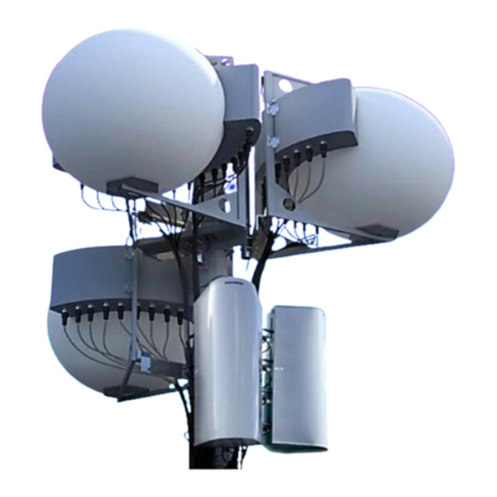
3.00 LSA lifting and installtions 3.10 LSA lifting equipment preparations Antenna installation location may vary from point to point in facing different terrains and environments; only the appropriate material handling machine, lifting equipment, and working platform are to be deployed with a certified operator. 3.20 Lifting planning and execution The installation and operations specialist shall plan the execution works according to the... - Page 8 3.34 LSA antenna installation (sample picture of antenna installed on-site) MS LSA Installation & Alignment General Guide Rev1 110924 Page 8 of 19...
- Page 9 3.35 LSA antenna leveling steps (for horizontal setting) Step 1 Digital gauge calibration to zero "0" level Target level is 0˚ (zero) ≤0.2˚ Place the digital gauge on the rear frame Step 2 top center. Place the digital gauge on the right Step 3 frame top center.
-
Page 10: Lsa Product Configurations (Example Models)
4.00 LSA product formation 4.10 LSA product configurations (example models) Lens Nos of Beam/R Left Top Left Top Tilt Model Band Frequency Tilt Up Size Rows Angle Angle Down MS-24H180 1695-2690 MHz 52.5° 57.5° -4.3° 4.3° MS-16H120 1695-2690 MHz 56.2° 48.8°... -
Page 11: Lsa Tilt Adjustment (Elevation)
5.00 LSA tilt adjustment (elevation) 5.10 Planning and execution Installation specialists have the option to pre-tilt the antenna angle before the lifting and installation of the antenna. That may help in reducing the work load and safety concern when performing adjustment on-site. 5.20 Antenna tilt configuration types (elevation angle) 5.21... -
Page 12: S" Ret Motor Connection And Operations
5.40 "S" RET motor connection and operations (example of MS-12H180 sn: #10) 5.41 Motor installation and connection "S" RET motor AISG daisy chain cable Female output Female Male Male input 2 Group of 6 motors Group Group External output (Female) External input (Male) Amphenol AISG laptop application 5.42... - Page 13 5.44 Plan view connector layout 5.45 Antenna connector port table 5.46 Group 1 display information and reference Group 1 display Display: Beam 1 (reference as RET 01) Display: Beam 2 (reference as RET 02) Display: Beam 3 (reference as RET 03) Display: Beam 4 (reference as RET 04) Display: Beam 5 (reference as RET 05) Display: Beam 6 (reference as RET 06)
- Page 14 Group 1 repeat beam 2 to beam 6 display as follows: RET 02 Info: R2 (HB2,P3,4) RET 03 Info: R3 (HB3,P5,6) RET 04 Info: R4 (HB4,P7,8) RET 05 Info: R5 (HB5,P9,10) RET 06 Info: R6 (HB6,P11,12) 5.48 Group 2 display information and reference Group 2 display Display: Beam 7 (reference as RET 07) Display: Beam 8 (reference as RET 08)
-
Page 15: Fixed Tilt-Factory Set
(example of MS-SLP-AXX Series) MS-18H90 MS-12H90 MS‐8H120 MS‐16H120 MS-18F45 MS-12F45 MS-8F60 MS-16F60 MS-8H60 MS-6H90 MS-48H180 MS-24H180 MS-8F30 MS-6F45 MS-48F90 MS-24F90 6.20 Model setting and assembly configuration table MS LSA Installation & Alignment General Guide Rev1 110924 Page 15 of 19... -
Page 16: Slp Parts Description And Configuration Overview
6.30 SLP parts description and configuration overview 6.31 Main base plate (Ball 120cm Max & Ball 180cm) Ball 120cm Max Ball 180cm 6.32 Left/Right base plate (TILT, SET 1, SET 2) & 120/180 center plate SET 2 RIGHT SET 1 LEFT SET 2 LEFT SET 1 RIGHT 180 CENTER... -
Page 17: Slp Mounting-On Antenna And Positioning Guide
7.00 SLP mounting-on antenna and positioning guide 7.10 Planning and execution Installation specialists should plan the mounting and adjustment works on deployed antenna models; advance on antenna model SLP assembly and configuration will be much helpful in reducing on-site assembly work load and safety concern. 7.20 SLP positioning guide 7.21... -
Page 18: Slp Pointing Guide Line
7.40 SLP pointing guide line 7.41 SLP laser-pointing projected view (example of MS-48F90) Beam Beam Laser Position Laser Position Angle Angle Centre Laser Left top laser Right top laser -52.5 +57.5 Left bottom laser -57.5 0/0° Right bottom laser +52.5 Beam 37 - 48 (4 Row 4) -12.9... -
Page 19: Lsa Antenna Position Confirm And Secure With Marking
7.50 LSA antenna position confirm and secure with marking (Repeat same process for another antenna positioning.) Building structure Adjustable support pole Custom-Make bracket Building structure On-site and recording as reference for position pointed MS LSA Installation & Alignment General Guide Rev1 110924 Page 19 of 19...
Need help?
Do you have a question about the MS-48H180 and is the answer not in the manual?
Questions and answers