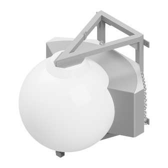
Matsing MS-48F90 General Manual
Large sphere antenna lsa tilt adjustment & "s" ret motor
Hide thumbs
Also See for MS-48F90:
- Instruction manual (8 pages) ,
- Installation manual (19 pages) ,
- Installation and alignment manual (18 pages)
Summary of Contents for Matsing MS-48F90
- Page 1 LSA Tilt Adjustment & "S"RET Motor General Guide ( Large Sphere Antenna) www.matsing.com technicalsupport@matsing.com phone: (800) 867-6429...
-
Page 2: Table Of Contents
Table Of Content 1.00 Large Sphere Antenna's (LSA) Product Overview 1.10 LSA with FIXED TILT -Factory Set (Sample Models) 1.11 FIXED TILT Model 1.12 FIXED TILT Model 1.20 LSA with MANUAL TILT (Sample Models) 1.21 MANUAL TILT Model 1.22 MANUAL TILT Model 1.30 LSA with "S RET Motor (Sample Models) 1.31... -
Page 3: Large Sphere Antenna's (Lsa) Product Overview
Large Sphere Antenna's (LSA) Product Overview 1.10 LSA with FIXED TILT -Factory Set (Sample Models) 1.11 FIXED TILT Model 1.12 FIXED TILT Model MS-48F90 MS-16F60 1.20 LSA with MANUAL TILT (Sample Models) 1.21 MANUAL TILT Model 1.22 MANUAL TILT Model... -
Page 4: Group X 6 Motor Model
1.33 1.34 1 Group x 6 Motor Model 1 Grp x 6 Motor + 1 Grp x 3 Motor Model MS-9SH90-FWB MS-12.6DB180 Group 1 Group 2 Group 1 1.35 1.36 2 Groups x 4 Motor Model 1 Group x 4 Motor Model MS-8.4DB120 MS-8C60 Group 1... -
Page 5: Lsa Manual Tilt & "S" Ret Motor Kit Assembly Parts & Tools
2.00 LSA Manual Tilt & "S" RET Motor Kit Assembly Parts & Tools 2.10 Manual Tilt Assembly Parts & Tools (Example Type 1) M4 x 20mm Ø16 x 6mm(t) Shaft M4 x 16mm Shaft Stopper PH Screw Bearing Retainer Handle PH Screw M4 x 6mm M4 x 4mm... -
Page 6: Manual Tilt Adjustment
Step 5: Adjust Handle & Step 6: Ensure Handle Tighten Shaft Stopper Smooth and Adjustable 2.12 Manual Tilt Adjustment Step 1: Tilt Stopper Loosening Step 2: Adjusting the Tilt Step 3: Tilt Stopper Tightening By hand or use screw driver to turn Screw Driver to loosen the Screw Driver to Tighten Back the shaft handle for adjustment... - Page 7 Ø16 x 6mm(t) L=28mm Hex Bottom Mount RET Water M4 x 12mm Bearing Retainer Adaptor Gasket Guard Interface Hex Cap Screw M4 x 4mm M3 x 11mm "S" RET Motor RET Interface Pre-Assembly Hex Screw PH Screw AISG Daisy Chain Cable 2.21 S RET Motor Kit without RET Gasket Adaptor Assembly Process (Reverse for Dis-Assembly) Step 1: Insert Bearing...
- Page 8 Step 5: "S" RET Motor And Step 6: Align/Insert "S" RET Interface Alignment Motor & Tighten Step 7: Align AISG Daisy Step 8: Repeat Same Chain Cable & Tighten Process for Other Motor 2.30 "S" RET Motor Kit with RET Gasket Adaptor Assembly Parts & Tools (Example Type 3) Hex Key #2 for M4 Hex Screw Screw Driver Hex Key #3 for M4 Hex Cap Screw...
- Page 9 RET Water M4 x 20mm Bottom Mount Interface Guard Hex Cap Screw Gasket "S" RET Motor RET Interface Pre-Assembly AISG Daisy Chain Cable 2.31 "S" RET Motor Kit with RET Gasket Adaptor Assembly Process (Reverse for Dis-Assembly) Step 1: Step 2: Insert Bearing Insert Lead Screw Gasket Retainer &...
- Page 10 Step 5: Insert Hex Adaptor Step 6: Insert RET Interface & Tighten Pre-Assembly Step 7: Tighten RET Step 8: Align/Insert "S" Interface Pre-Assembly RET Motor & Tighten Step 9: Insert AISG Daisy Step 10: Repeat Same Chain Cable & Tighten Process for Other Motor MS LSA Antenna Tilt Adjustment &...
-
Page 11: Lsa "S" Ret Installation & Controller Display
3.00 LSA "S" RET Installation & Controller Display 3.10 "S" RET Installation/Connection (Example of MS-12H180 sn: #10) MS-12H180 2 Group of Motors Connection (Max 6 Per Group) Group 1 Group 2 External Input (Male) External Output (Female) Amphenol AISG Laptop Application *** Repeat Same Process For Group 2 Testing MS LSA Antenna Tilt Adjustment &... -
Page 12: Antenna Connector Layout
3.20 Antenna Connector Layout 3.30 Antenna Connector Port Table BEAM 6 BEAM 5 BEAM 4 BEAM 3 BEAM 2 BEAM 1 PORT PORT PORT PORT PORT PORT PORT PORT PORT PORT PORT PORT (+45) (-45) (+45) (-45) (+45) (-45) (+45) (-45) (+45) (-45) -
Page 13: Group 1 - Information & Display
3.50 Group 1 - Information & Display Display: Beam 1 (Reference as RET 01) Display: Beam 2 (Reference as RET 02) Display: Beam 3 (Reference as RET 03) Display: Beam 4 (Reference as RET 04) Display: Beam 5 (Reference as RET 05) Display: Beam 6 (Reference as RET 06) Model s/no. -
Page 14: Group 2 - Information & Display
Display: Beam 5 (Refer as RET 05) RET 05 Info: R5 (HB5,P9,10) Display: Beam 6 (Refer as RET 06) RET 06 Info: R6 (HB6,P11,12) 3.60 Group 2 - Information & Display Display: Beam 7 (Reference as RET 07) Display: Beam 8 (Reference as RET 08) Display: Beam 9 (Reference as RET 09) Display: Beam 10 (Reference as RET 10) Display: Beam 11 (Reference as RET 11) - Page 15 Display: Beam 9 (Refer as RET 09) RET 09 Info: R9 (HB9,P17,18) RET 10 Info: R10 (HB10,P19,20) Display: Beam 10 (Refer as RET 10) RET 11 Info: R11 (HB11,P21,22) Display: Beam 11 (Refer as RET 11) RET 12 Info: R12 (HB12,P23,24) Display: Beam 12 (Refer as RET 12) MS LSA Antenna Tilt Adjustment &...


Need help?
Do you have a question about the MS-48F90 and is the answer not in the manual?
Questions and answers