Table of Contents
Advertisement
Quick Links
R
GENMAX GENERATOR
INVERTER GENERATOR
USER'S MANUAL
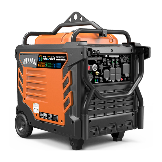
GM11000iET
TRI-FUEL INVERTER GENERATOR
WARNING: SAVE THIS MANUAL FOR FUTURE REFERENCE
This manual contains important information regarding safety. Operation,
maintenance and storage of this product. Before use, read carefully and
understand all cautions, warnings, instructions and product labels. Failure to do
so could result in serious personal injury and/or property damage.
Advertisement
Table of Contents

Related Manuals for GENMAX GM11000iET


Summary of Contents for GENMAX GM11000iET
- Page 1 GENMAX GENERATOR INVERTER GENERATOR USER'S MANUAL GM11000iET TRI-FUEL INVERTER GENERATOR WARNING: SAVE THIS MANUAL FOR FUTURE REFERENCE This manual contains important information regarding safety. Operation, maintenance and storage of this product. Before use, read carefully and understand all cautions, warnings, instructions and product labels. Failure to do...
- Page 2 DISCLAIMERS: All information, illustrations and specifications in this manual are based on the latest information available at the time of publishing. The illustrations used in this manual are intended as representative reference views only. Moreover, because of our continuous product improvement policy, we may modify information, illustrations and/or specifications to explain and/or exemplify a product, service or maintenance improvement.
- Page 3 DESCRIPTION OF FITTINGS Spark Plug Socket Wrench Dual-Purpose Screwdriver Funnel Phillips and slot blade Used in spark plug maintenance, screwdriver used for generator It's used to oil the generator. inspection, and installation. maintenance. Remote Control Key Battery Charger 1100ml 10W30 Oil Used to remotely start and stop Used to charge the battery Be sure to add oil before starting...
- Page 4 NG Quick Connector Quick Plug Joint Inside Diameter ∅20.2 Inside Diameter NPT 1/2 Outside Diameter ∅35 Protective Cover Used to change a natural gas pipeline interface. Note: Actual tools may differ in appearance or design from image shown.
-
Page 5: Limited Warranty
2. WHO GIVES THIS WARRANTY (WARRANTOR): CHONGQING DINKING POWER MACHINERY CO., LTD 3. WHO RECEIVES THIS WARRANTY(PURCHASER):The original purchaser (other than for purposes of resale) of the Genmax's inverter. 4. WHAT PRODUCTS ARE COVERED BY THIS WARRANTY: Any portable generator supplied or manufactured by Warrantor. -
Page 6: Table Of Contents
TABLE OF CONTENTS LIMITED WARRANTY SAFETY WARNING SAFETY INSTRUCTIONS NAMES OF COMPONENTS CONTROL FUNCTIONS PREPARATIONS 1.Fuel............................14 2.Oil.............................14 3.Pre-operation Inspection......................15 STARTING UP THE GENERATOR SHUTTING DOWN THE GENERATOR USING THE GENERATOR 1.Service Environment of the Generator..................22 2.Generator Wiring........................22 3.Generator Grounding.........................23 4.Changing the Neutral Point......................24 5.Battery Charging........................24 SERVICE AND MAINTENANCE 1.Spark Plug Inspection......................26... -
Page 7: Safety Warning
SAFETY WARNING Personal and property safeties of you and others are very vital. Please read the Safety Warning in the User's Manual and the decals of the generator set carefully.The Safety Warning can alert you to those potential hazards that could harm you and others. In front of each Safety Warning, there is one of four words "DANGER"... -
Page 8: Safety Instructions
SAFETY INSTRUCTIONS Before operating the generator, it will help you avoid accidents to read and understand the Manual and familiarize yourself with the safe operation procedures of the generator. Please do not use in humid Please do not use indoors environment Do not directly connect to the Please do not smoke when refueling... - Page 9 SAFETY INSTRUCTIONS SAFETY LABELS AND DECALS 77 ℉/25℃...
-
Page 10: Names Of Components
NAMES OF COMPONENTS ① Fuel Tank Cap: Open the fuel tank cap and fill with ⑦ Right Outer Cover: Unscrew the bolts, remove the proper amount of gasoline. outer cover, and add or change the oil. ② ⑧ Muffler: Avoid contact until the engine is cooled Recoil Handle: Pull to start the engine. -
Page 11: Control Functions
. Unplug the devices and reduce GENMAX. The connector sockets is only used to connect two the load. Push in the reset breaker to reset it. inverter generators. They can not used for AC power output. - Page 12 CONTROL FUNCTIONS OUTPUT DESCRIPTION OF THE AC SOCKET When the voltage selector switch is set to 120V ONLY The voltage selector switch is set to 120V ONLY. Output voltage can only be 120V and current 50A. Single socket output 120V(Voltage)×50A(Current)=6000W(Output Power) 120V The total power output of the socket must not exceed the ATTENTION:...
- Page 13 CONTROL FUNCTIONS When the voltage selector switch is set to 120/240V (Suitable for parallel) The voltage selector switch is set to 120/240V. The voltage is 120/240V and two generators can be connected in parallel. The output voltage is 120/240V, and the current is only 35.4A without parallel connection.
- Page 14 CONTROL FUNCTIONS DIGITAL DISPLAY CENTER ① : Represents single run time, goes from 0 at ③ VOLTAGE: Voltage display: 120V and 240V switch every each startup. 16 seconds. ② : Represents total operation time of the ④ FREQUENCY: Frequency display. generator.(Tip: The total operation time shall start to ⑤...
-
Page 15: Preparations
PREPARATIONS Fuel DANGER • Fuel is flammable and toxic, please read the Safety Instruction carefully before refueling; • Do not fuel too full, otherwise fuel will spill after fuel tank is warmed; • After refueling, confirm that the fuel tank cap has been tightened. ATTENTION •... -
Page 16: Pre-Use Inspection
PREPARATIONS Pre-use Inspection WARNING Even if the generator is not in service, its important component may suddenly fails. Before the generator is started up, if any of following components is unable to work properly, please inspect and repair carefully. Tip: The condition of the generator shall be inspected before using every time. Pre-operation inspection Project Possible Causes... -
Page 17: Starting Up The Generator
STARTING UP THE GENERATOR Remove the load from all output ends; Connect battery line before first use: 1. Remove the left panel cover; 2. A quick-connect battery plug is pre-installed on the battery. Remove the cable tie securing the plugs, align colors, then push firmly to connect them. - Page 18 STARTING UP THE GENERATOR Press the LOW IDLE Switch to "OFF"; Press the Main Switch to "ON"; Select Boot Mode: a. Recoil Start: Pull the starting handle to start the generator. b. Button Start: Press the button to start the generator. c.
- Page 19 STARTING UP THE GENERATOR Remote Control Key Dormancy When generator stops running for 5 days (120hours), while the main switch is not turned off, the remote control key cannot be used to start the generator again. At this time, you need to turn off the main switch and turn it on again, or press the one-key start button (or hand start) to start the generator, and the remote control key will be reactivated.
- Page 20 STARTING UP THE GENERATOR DANGER Fire and explosion hazard. Always turn the propane tank (or methane) valve to the fully closed position if not running the generator on propane(or methane). WARNING When using the generator with propane(or methane), make sure there is no possible ignition source close to the generator.
- Page 21 STARTING UP THE GENERATOR INVERTER PARALLEL KIT OPERATION 50A Parallel Kits This parallel kit is intended to be used Round Connector (Black) only with GENMAX inverter generators. Ground Connectors (Ring) Please read safety information below Square Connector (Black) Connectors(Red) before proceeding.
-
Page 22: Shutting Down The Generator
SHUTTING DOWN THE GENERATOR Unplug the power cord; Select Stop Mode: a. Button Stop: Press the button to turn off the generator. b. Remote Stop: Press the "STOP" button on the remote control to turn off the generator. Press the Main Switch to "OFF"; Set the Fuel Source Wwitch to the off position. -
Page 23: Using The Generator
USING THE GENERATOR Service Environment of the Generator • Applicable temperature: 23℉~104℉ (-5°C~ 40°C); • Applicable humidity: below 95%; • Applicable altitude: regions below 1,500 m (It shall be used by reducing power in regions above 1,000 m). Standard atmospheric condition •... -
Page 24: Generator Grounding
USING THE GENERATOR Connection of AC power WARNING All electrical equipment shall be disconnected before inserting the plug. ATTENTION • Make sure that all electrical equipment, including wires and plugs, are in good condition before connecting to the generator; • Make sure that all loads driven by the generator are within rated load range; •... -
Page 25: Changing The Neutral Point
USING THE GENERATOR Changing the Neutral Point This generator is "neutral floating" state, if you want to change to a "neutral bonded" state, insert the Bonding Plug into the output socket of the generator to change the neutral floating to neutral bonded status. Special Bonding Plug must be purchased NEMA L14-30P separately. -
Page 26: Service And Maintenance
SERVICE AND MAINTENANCE Good maintenance and service is the best guarantee for safe, economical and zero-failure operation. It also contributes to environmental protection. In order to keep the generator in good condition, you must inspect and maintain it regularly. The maintenance schedule is as follows: Then every three Maintenance cycle... -
Page 27: Spark Plug Inspection
SERVICE AND MAINTENANCE WARNING Please shut down the engine first before performing any maintenance. The engine shall be placed in a horizontal position. In order to prevent the engine from starting up, separate spark plug cap shall be separated from spark plug. Do not use it indoors or use it in a tunnel, cave or other places ventilated poorly. -
Page 28: Adjustment Of The Carburetor
SERVICE AND MAINTENANCE Install the spark plugs in reverse order of removal. Spark plug torque: 22.5±2.5N.m(199±22in-lb) Tip: If there is no torque wrench when installing the spark plug, a better estimation method is to screw it 1/4-1/2 turns by force after screwing it in place, but the spark plug shall be screwed to specified torque as soon as possible. Adjustment of the Carburetor The carburetor is an important components of the engine. -
Page 29: Oil Filter
SERVICE AND MAINTENANCE Unscrew oil dipstick; Refill oil to a proper level, tighten oil dipstick, cover external cover plate and tighten the knob. Recommended oil: SAE S10W/30 Oil grade: API standard Model SJ or higher Volume: 0.3gal(1.1L) Oil Filter It is recommended to clean the oil filter after the first operation of the generator. After that, it will be cleaned every 50 hours. -
Page 30: Fuel Filter Screen
SERVICE AND MAINTENANCE Clean foam cleaner element with cleaning solvent and blow it dry, Put a few drops of oil on the filter element. ATTENTION Be sure not to twist the foam cleaner element forcibly to avoid damage. Put foam cleaner element into air cleaner; Tip: Make sure that the surface of foam cleaner element is in close contact with air cleaner, and there shall be no gap leaking air. -
Page 31: Storage And Transport
STORAGE AND TRANSPORT Generator Storage If it is stored long-term, in order to prevent aging, you shall take some storage measures. Shut down generator. Open fuel tank cap, to take out fuel filter screen. Pump all fuel in fuel tank into special fuel tank, and then reassemble fuel tank cap back. -
Page 32: Generator Transport
STORAGE AND TRANSPORT Gently pull startup handle until you feel resistance, allowing both inlet valve and exhaust valve to be closed. Disconnect the battery cable. Place the generator set in a clean and dry area. Generator transport • When the generator set is transported, it shall be ensured that there is no fuel spilling; •... -
Page 33: Troubleshooting
TROUBLESHOOTING... - Page 34 TROUBLESHOOTING...
-
Page 35: Technical Parameters
TECHNICAL PARAMETERS Item GM11000iET Rated Power (kW) 8.5(GAS.)/8.0(LPG)/6.8(NG) Max. Power (kW) 11(GAS.)/9.5(LPG)/8.4(NG) 460i Engine Model Input valve:0.10~0.15 mm, Output valve:0.15~0.20 mm Valve Clearance 92×69 Stroke × Bore (mm) Engine Type 4-stroke Displacement (cc) Gas Distribution Mode Cooling Mode Forced cooling wind... -
Page 36: Choosinga Generator
CHOOSING A GENERATOR... - Page 37 In production management, based on orderly, efficient, scientific principles. trying to do as better as possible in product design, development, production, inspection, etc. to make our production can keep orderly. And will continue to make improvement to make sure that keep the competitiveness.
Need help?
Do you have a question about the GM11000iET and is the answer not in the manual?
Questions and answers
need schematic for gm11000iet.
The schematic for the GENMAX GM11000iET is referred to as the "GM11000iET SAMS Exploded View," which can be downloaded from the user manual page.
This answer is automatically generated