Table of Contents
Advertisement
R
GENMAX GENERATOR
INVERTER GENERATOR
USER'S MANUAL
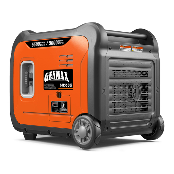
GM5500i
GM6000iED
Portable Inverter Generator
Portable Inverter Generator
5000 Running Watts | 5500 Peak Watts
5250(GAS.)/4750(LPG) Running Watts | 6000(GAS.)/5500(LPG) Peak Watts
WARNING: SAVE THIS MANUAL FOR FUTURE REFERENCE
This manual contains important information regarding safety. Operation,
maintenance and storage of this product. Before use, read carefully and
understand all cautions, warnings, instructions and product labels. Failure to
do so could result in serious personal injury and/or property damage.
Advertisement
Table of Contents

Related Manuals for GENMAX GM5500i


Summary of Contents for GENMAX GM5500i
- Page 1 GENMAX GENERATOR INVERTER GENERATOR USER'S MANUAL GM5500i GM6000iED Portable Inverter Generator Portable Inverter Generator 5000 Running Watts | 5500 Peak Watts 5250(GAS.)/4750(LPG) Running Watts | 6000(GAS.)/5500(LPG) Peak Watts WARNING: SAVE THIS MANUAL FOR FUTURE REFERENCE This manual contains important information regarding safety. Operation, maintenance and storage of this product.
- Page 2 DISCLAIMERS: All information, illustrations and specifications in this manual are based on the latest information available at the time of publishing. The illustrations used in this manual are intended as representative reference views only. Moreover, because of our continuous product improvement policy, we may modify information, illustrations and/or specifications to explain and/or exemplify a product, service or maintenance improvement.
-
Page 3: Limited Warranty
3. WHO RECEIVES THIS WARRANTY(PURCHASER):The original purchaser (other than for purposes of resale) of the Genmax's inverter.4. WHAT PRODUCTS ARE COVERED BY THIS WARRANTY: Any portable generator supplied or manufactured by Warrantor.5. WHAT IS COVERED UNDER THIS WARRANTY: Substantial defects on material and workmanship which occur within the durat ion of the warranty period. -
Page 4: Table Of Contents
TABLE OF CONTENTS LIMITED WARRANTY SAFETY WARNING SAFETY INSTRUCTIONS NAMES OF COMPONENTS CONTROL FUNCTIONS PREPARATIONS 1.Fuel............................11 2.Oil...............................11 3.Pre-operation inspection......................12 STARTING UP THE GENERATOR SHUTTING DOWN THE GENERATOR USING THE GENERATOR 1.Service environment of the generator..................17 2.Generator wiring........................17 3.Generator grounding.........................18 SERVICE AND MAINTENANCE 1.Spark plug inspection.......................20 2.Adjustment of the carburetor.....................21 3.Replacement of oil........................21... -
Page 5: Safety Warning
SAFETY WARNING Personal and property safeties of you and others are very vital. Please read the Safety Warning in the User's Manual and the decals of the generator set carefully.The Safety Warning can alert you to those potential hazards that could harm you and others. In front of each Safety Warning, there is one of four words "DANGER"... -
Page 6: Safety Instructions
SAFETY INSTRUCTIONS Before operating the generator, it will help you avoid accidents to read and understand the Manual and familiarize yourself with the safe operation procedures of the generator. Please do not use in humid Please do not use indoors environment Please do not connect it to Please do not smoke when refueling... - Page 7 SAFETY INSTRUCTIONS SAFETY LABELS AND DECALS Before using the generator, please read the operation manual.Be careful with the shock hazard.Be careful, the fuel is flammable, do not add the fuel when the engine is running.
-
Page 8: Names Of Components
NAMES OF COMPONENTS Fuel tank cap Telescopic rod Control panel LPG Port (GM6000iED only) Left enclosure Start handle Muffler Wheel Right enclosure... -
Page 9: Control Functions
NEUTRAL FLOATING AC 120V/240V AC BREAKER NEUTRAL FLOATING AC BREAKER CONTROL PANEL FEATURES GM5500i ① 120-Volt, 20-Amp Duplex Outlet (NEMA 5-20R): ⑦ AC Breaker: If the inverter is overloaded, the The outlet is capable of carrying a maximum of 20 reset breaker will trip to block current. - Page 10 CONTROL FUNCTIONS CONTROL PANEL FEATURES GM6000iED ① 120-Volt, 20-Amp Duplex Outlet (NEMA 5-20R): ⑩ CO Alarm: Flashing red light: dangerous levels of The outlet is capable of carrying a maximum of 20 carbon monoxide gas have built up leave immediately amps.
- Page 11 CONTROL FUNCTIONS DIGITAL DISPLAY CENTER ① HOURS: Represents single run time, goes from 0 ⑤ FREQUENCY: Frequency display. at each startup. ⑥ LOAD: Load power display. ② HOURS: Represents total operation time of the ⑦ POWER: Green light means normal operation. generator.
-
Page 12: Preparations
PREPARATIONS Fuel DANGER • Fuel is flammable and toxic, please read the Safety Instruction carefully before refueling; • Do not fuel too full, otherwise fuel will spill after fuel tank is warmed; • After refueling, confirm that the fuel tank cap has been tightened. ATTENTION •... -
Page 13: Pre-Operation Inspection
PREPARATIONS Pre-use Inspection WARNING Even if the generator is not in service, its important component may suddenly fails. Before the generator is started up, if any of following components is unable to work properly, please inspect and repair carefully. Tip: The condition of the generator shall be inspected before using every time. Pre-operation inspection Fuel •... -
Page 14: Starting Up The Generator
STARTING UP THE GENERATOR GM5500i Startup Procedure Remove the load from all output ends; Connect battery line before first use: 1. Open the oil maintenance cover; 2. Connect the positive and negative electrodes of the battery. Press the ECO switch to "OFF";... - Page 15 STARTING UP THE GENERATOR GM6000iED Startup Procedure Remove the load from all output ends; Connect battery line before first use: 1. Open the oil maintenance cover; 2. Connect the positive and negative electrodes of the battery. Select the Fuel: a. Gasoline: Turn the oil/gas switch to gasoline; b.
- Page 16 STARTING UP THE GENERATOR Select Boot Mode: a. Hand Starting: Pull the starting handle to start the generator. b. One Button to Start: Press the one-click start button to start the generator. c. Remote Start: Press the "START" button on the remote control to start the generator. Plug in after started.
-
Page 17: Shutting Down The Generator
SHUTTING DOWN THE GENERATOR GM5500i shutdown procedure Unplug the power cord; Turn the four in-one switch to "OFF", the generator stops running. GM6000iED shutdown procedure Unplug the power cord; Select Stop Mode: a. One Button to Start: Press the one-click start button to turn off the generator. -
Page 18: Using The Generator
USING THE GENERATOR Service environment of the generator • Applicable temperature: -5°C ~ 40°C; • Applicable humidity: below 95%; • Applicable altitude: regions below 1,500 m (It shall be used by reducing power in regions above 1,000 m). Standard atmospheric condition •... -
Page 19: Generator Grounding
USING THE GENERATOR Connection of AC power WARNING All electrical equipment shall be disconnected before inserting the plug. ATTENTION • Make sure that all electrical equipment, including wires and plugs, are in good condition before connecting to the generator; • Make sure that all loads driven by the generator are within rated load range; •... -
Page 20: Service And Maintenance
SERVICE AND MAINTENANCE Good maintenance and service is the best guarantee for safe, economical and zero-failure operation. It also contributes to environmental protection. In order to keep the generator in good condition, you must inspect and maintain it regularly. The maintenance schedule is as follows: Then every three Maintenance cycle... -
Page 21: Spark Plug Inspection
SERVICE AND MAINTENANCE WARNING Please shut down the engine first before performing any maintenance. The engine shall be placed in a horizontal position. In order to prevent the engine from starting up, separate spark plug cap shall be separated from spark plug. Do not use it indoors or use it in a tunnel, cave or other places ventilated poorly. -
Page 22: Adjustment Of The Carburetor
SERVICE AND MAINTENANCE Install the spark plugs in reverse order of removal. Spark cold torque: 22.5±2.5 N.m Tip: If there is no torque wrench when installing the spark plug, a better estimation method is to screw it 1/4-1/2 turns by force after screwing it in place, but the spark plug shall be screwed to specified torque as soon as possible. Adjustment of the carburetor The carburetor is an important components of the engine. -
Page 23: Air Filter
SERVICE AND MAINTENANCE Unscrew oil dipstick; Refill oil to a proper level, tighten oil dipstick, cover external cover plate and tighten the knob. Recommended oil: SAE S10W/30 Oil grade: API standard Model SJ or higher Volume: 0.12gal Air filter Dirty air cleaner may prevent air from flowing into the carburetor. In order to prevent failure of the carburetor, please maintain air cleaner regularly. -
Page 24: Fuel Filter Screen
SERVICE AND MAINTENANCE 1. Reassemble empty air cleaner cap back to original position, and tighten screws; 2. Assemble left outer cover and tighten bolts. Fuel filter screen WARNING Be sure not to open fuel tank of the generator in a place where smoking or with flame. 1. -
Page 25: Storage And Transport
STORAGE AND TRANSPORT Generator storage If it is stored long-term, in order to prevent aging, you shall take some storage measures. Shut down generator. Open fuel tank cap, to take out fuel filter screen. Pump all fuel in fuel tank into special fuel tank, and then reassemble fuel tank cap back. -
Page 26: Generator Transport
STORAGE AND TRANSPORT Gently pull startup handle until you feel resistance, allowing both inlet valve and exhaust valve to be closed. Disconnect the battery cable. Place the generator set in a clean and dry area. Generator transport • When the generator set is transported, it shall be ensured that there is no fuel spilling; •... -
Page 27: Troubleshooting
TROUBLESHOOTING... - Page 28 TROUBLESHOOTING...
-
Page 29: Technical Parameters
TECHNICAL PARAMETERS Item GM5500i GM6000iED Rated Power (kW) 5.25(GAS.)/4.75(LPG) Max. Power (kW) 6.0(GAS.)/5.5(LPG) 180F/P-2 180F/P-2 Engine Model 80x62 80x62 Stroke x Bore (mm) Engine Type 4-stroke 4-stroke Displacement (cc) Gas Distribution Mode Cooling Mode Forced cooling wind Rated Speed (RPM) -
Page 30: Circuit Diagram
CIRCUIT DIAGRAM GM5500i SCHEMATICS... - Page 31 CIRCUIT DIAGRAM GM6000iED SCHEMATICS...
-
Page 32: Choosinga Generator
CHOOSING A GENERATOR... - Page 33 In production management, based on orderly, efficient, scientific principles. trying to do as better as possible in product design, development, production, inspection,etc. to make our production can keep orderly . And will continue to make improvement to make sure that keep the competitiveness.
Need help?
Do you have a question about the GM5500i and is the answer not in the manual?
Questions and answers