
Related Manuals for Wacker Neuson GS 12Ai


Summary of Contents for Wacker Neuson GS 12Ai
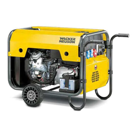
- Page 1 Operator's manual Portable Generator Model GS 12Ai Document 5100004227 Issue 07-2019 Revision Language English...
- Page 2 Neuson Produktion GmbH & Co. KG. Any breach of the statutory provisions, in particular the protection of copyright, will lead to civil and criminal prosecution. Wacker Neuson Produktion GmbH & Co. KGis constantly working on the improvement of its products as part of the technical further development. Therefore, we reserve the right to make changes to the illustrations and descriptions in this documentation without incurring any obligation to make changes to machines already delivered.
-
Page 3: Table Of Contents
Use of the manual Storing the manual Accident prevention regulations Further information Target group Symbol explanation Wacker Neuson representative Limitation of liability Identification of the machine Safety Information Singal words used in this manual Machine description and intended use safety guidelines for operating the machine... - Page 4 Troubleshooting Wire colours 7.10 Engine wiring 7.11 Generator and receptacle wiring 7.12 Long-term storage Technical data GS 12Ai Combustion engine Disposal Disposal of waste electrical and electronic equipment EC declaration of conformity...
-
Page 5: Foreword
This operator's manual is not a manual for extensive maintenance or repair work. Such work should be carried out by Wacker Neuson service or by technically trained personnel. The Wacker Neuson machine should be operated and maintained in accordance with this operator's manual. An improper operation or improper maintenance can pose dangers. -
Page 6: Introduction
The information contained in this manual is based on machines which have been manufactured at the time of printing. Wacker Neuson reserves the right to amend this information without notification. -
Page 7: Target Group
2 Introduction Target group Note: Persons working with this machine must receive regular training about the risks and hazards of this machine. This operator's manual is aimed at the following persons: Operatives: These persons are introduced to the machine and informed about potential hazards arising from improper behavior. -
Page 8: Wacker Neuson Representative
The address of the manufacturer is located at the beginning of this operator's manual. Limitation of liability Wacker Neuson will refuse to accept liability for injuries to persons or for damage to materials in the following cases: Failure to comply with this manual. -
Page 9: Safety Information
Safety Information Machine Description and Intended Use This machine is a portable electric power source. The Wacker Neuson Portable Generator consists of a tubular steel frame surrounding a fuel tank, a gasoline engine, a control panel, and an electric alternator. The control panel includes controls and receptacles. -
Page 10: Safety Guidelines For Operating The Machine
3 Safety Information Safety Guidelines for Operating the Machine Operator qualifications Only trained personnel are permitted to start, operate, and shut down the machine. They also must meet the following qualifications: have received instruction on how to properly use the machine ... - Page 11 3 Safety Information NEVER enclose or cover the generator when it is in use or when it is hot. NEVER overload the generator. The total amperage of the tools and equipment attached to the generator must not exceed the load rating of the generator. NEVER operate the machine in snow, rain, or standing water.
-
Page 12: Operator Safety While Using Internal Combustion Engine
3 Safety Information Operator Safety while Using Internal Combustion Engine WARNING Internal combustion engines present special hazards during operation and fueling. Failure to follow the warnings and safety standards could result in severe injury or death. Read and follow the warning instructions in the engine owner’s manual and ... -
Page 13: Service Safety
ALWAYS keep the fuel lines in good condition and properly connected. Leaking fuel and fumes are extremely explosive. When replacement parts are required for this machine, use only Wacker Neuson replacement parts or those parts equivalent to the original in all types of... -
Page 14: Safety And Information Labels
4 Safety and Information labels Safety and information labels Your machine has adhesive labels containing the most important instructions and safety information. Keep all labels legible. Replace missing or illegible labels. The item numbers on the labels can be found in the parts book. Item Label Description... - Page 15 4 Safety and Information labels When connecting more than one piece of electric equipment, Special precautions must be taken. Read through the operator's manual.
-
Page 16: Lifting And Transporting
Your machine may be equipped with a lifting beam as shown in the illustration below. The lifting beam is available as an accessory kit (part number 0177442) from your Wacker Neuson dealer. Guidelines for lifting safety If your machine is equipped with a lifting beam, observe the following guidelines: The equipment used to lift the machine must have suitable dimensions and ... -
Page 17: Operation
The information in “Approximate Starting Power Requirements” is offered only as a general guideline to help you determine power requirements for different types of equipment. Check with your nearest Wacker Neuson dealer, or contact the manufacturer or dealer of the tool or appliance, if you have questions regarding power requirements. -
Page 18: Installation
6 Operation Approximate Starting Power Requirements Incandescent lights and appliances such as irons and hot plates, which use a resistive-type heating element, require the same wattage to start and run as is stated on their nameplates. Fluorescent and mercury lamps require 1.2–2 times their stated wattage to ... -
Page 19: Generator Derating
6 Operation Generator Derating All generators are subject to derating for altitude and temperature. Internal combustion engines, unless modified, run less efficiently at higher altitudes due to the reduction of air pressure. This translates into a lack of power and thus reduction in generator output. -
Page 20: Use Of Extension Cords
6 Operation Use of extension cords When a long extension cord is used to connect an appliance or tool to the generator, a voltage loss occurs—the longer the cord, the greater the voltage loss. This results in less voltage being supplied to the appliance or tool and increases the amount of current draw or reduces performance. - Page 21 6 Operation Minimum Extension cord Size 230V Volts Total length of cords in meters 230V 0 – 30 30 – 60 Amp rating Cross sectional area of wire in mm 0.75 Minimum Extension cord Size 400V 400V Amp rating Section of cord mm Max fuse Minimum Extension Cord Size Graph...
-
Page 22: Isolation Monitor
6 Operation Isolation Monitor Generator is equipped with an Isolation Monitor. The Isolation Monitor consists of a sensing module (a), a TEST button with light (b), a relay (c), and a breaker for each phase and neutral (d1-d4). The relay and the breakers are mechanically ganged together and operate as the main circuit breaker. -
Page 23: Control Panel
6 Operation Control panel The generator is protected by a 16 amp circuit breaker (a) located on the control panel. The circuit breaker protects the generator from severe overloads or short circuits. If the circuit breaker opens, turn the engine off immediately and determine the cause before restarting. -
Page 24: Before Starting
Open choke as engine warms (a2). Place main circuit breaker in closed position (e1). Allow the engine to warm up for a few minutes before attaching loads. On models GS 12Ai check function of the Isolation Monitor. See Section Isolation Monitor. -
Page 25: Stopping
6 Operation 6.10 Stopping Turn off and disconnect all tools and appliances attached to the generator. Place main circuit breaker in open position (e2). Turn engine switch to “OFF” (b1). Turn fuel valve off. Note: To stop engine quickly in an emergency, turn engine switch to "OFF". 6.11 Emergency stop procedure Procedure... -
Page 26: Maintenance
7 Maintenance Maintenance Periodic Maintenance Schedule The table below lists basic machine and engine maintenance. Tasks designated with check marks may be performed by the operator. Tasks designated with square bullet points require special training and equipment. Refer to the engine owner’s manual for additional information. Daily After the Every 6... -
Page 27: Engine Oil
7 Maintenance Engine oil Drain oil while engine is still warm. Remove oil fill cap (a), drain plug (b), and washer (c) to drain oil. Note: In the interests of environmental protection, place a plastic sheet and a container under the machine to collect any liquid which drains off. Dispose of this liquid in accordance with environmental protection legislation. -
Page 28: Servicing The Air Cleane
7 Maintenance Servicing the Air cleaner WARNING NEVER use gasoline or other types of low-flash point solvents for cleaning the air cleaner. A fire or explosion could result. NOTICE: NEVER run the engine without the air cleaner. Severe engine damage will occur. -
Page 29: Spark Plug
7 Maintenance Spark plug Clean or replace the spark plug as needed to ensure proper operation. Refer to your engine operator’s manual. WARNING The muffler becomes very hot during operation and remains hot for a while after stopping the engine. Do not touch the muffler while it is hot. Note: Refer to section “Technical Data”... -
Page 30: Maintaining The Fuel Filter
7 Maintenance Maintaining the Fuel Filter Change the in-line fuel filter (a) once a year or every 300 hours of operation. Check the fuel lines and fittings daily for cracks or leaks. Replace as needed. WARNING Gasoline is extremely flammable! Turn the engine off and allow the engine to cool before replacing the fuel filter. -
Page 31: Troubleshooting
7 Maintenance Troubleshooting Problem / symptom Cause / remedy Engine switch is on "Start" position. If the engine does not start, check that: Fuel valve on engine is open. Fuel tank has fuel Choke lever is in the correct position. The choke should be closed when starting a cold engine. -
Page 32: Engine Wiring
7 Maintenance 7.10 Engine wiring Ref. Description Ref. Description Spark plug Fuel cutoff solenoid Ignition coil Oil level switch Chargin coil Regulator rectifier Battery Main fuse Starter motor Engine switch... -
Page 33: Generator And Receptacle Wiring
7 Maintenance 7.11 Generator and receptacle wiring Ref. Description Ref. Description Rotor winding Filter (RIS) Automatic Voltage Regulator Hour meter Isolation Monitor Circuit breaker / Trip Relay 230V / 16A receptacle shuko Volt meter 250V / 16A receptacle CEE Main Stator winding 400V / 16A receptacle CEE 3-phase Key switch... -
Page 34: Long-Term Storage
7 Maintenance 7.12 Long-term storage Before storing generator for a long period of time: Turn the engine fuel valve to the OFF position. Disconnect the fuel line from the carburetor. Place open end of fuel line into a suitable container and open fuel valve to drain fuel from tank. WARNING Gasoline is extremely flammable. -
Page 35: Technical Data Gs 12Ai
8 Technical data Technical data GS 12Ai Designation Unit GS 12Ai Item number 5000620317 Limited-time running Power (LTP) 1~ Limited-time running Power (LTP) 3~ 11.1 Continuous Operating Power (COP) 1~ Continuous Operating Power (COP) 3~ Prime Power (PRP) 9.47 Length mm (in) 960 (37.8) -
Page 36: Combustion Engine
8 Technical data Combustion engine Designation Unit Manufacturer Honda Type of engine GX630R VXP2 SD Combustion method Four-cycle Cooling Air cooling Cylinders Displacement 688 (42) Fuel type Gasoline Fuel consumption l/h (gph us) 3.9 (1) Mixture preparation Carburettor Oil Specification SAE 10W-40 Oil capacity l (gal us) -
Page 37: Disposal
9 Disposal Disposal Disposal of waste electrical and electronic equipment Professional disposal of this machine avoids negative effects on human health and the environment, helps with the targeted treatment of pollutants and makes it possible to recycle valuable raw materials. For customers in EU countries This machine is subject to the European directive for old electrical and electronic equipment (Waste Electrical and Electronic Equipment (WEEE)), as well as the... -
Page 38: Ec Declaration Of Conformity
Original Declaration of conformity...
Need help?
Do you have a question about the GS 12Ai and is the answer not in the manual?
Questions and answers