
Related Manuals for Wacker Neuson GS 8.5V


Summary of Contents for Wacker Neuson GS 8.5V
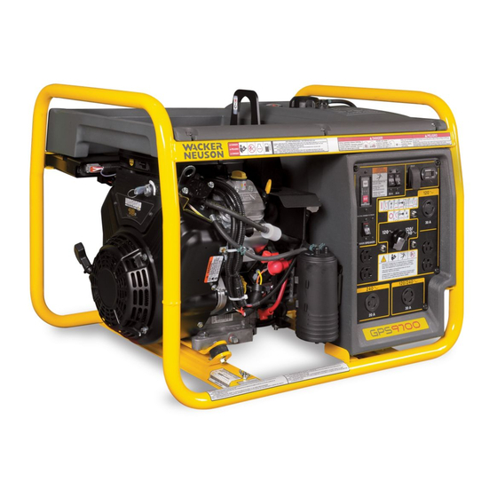
- Page 1 0174423en 0809 Generator GS 8.5V GPS 8500 GS 9.7V GPS 9700 REPAIR MANUAL...
-
Page 3: Foreword
Expectations This manual provides information and procedures to safely operate and main- tain the above Wacker Neuson model(s). For your own safety and to reduce the information in risk of injury, carefully read, understand, and observe all instructions described this manual in this manual. - Page 4 Foreword GPS 8500/GPS 9700 with local laws regarding spark arresters, consult the engine distributor or the local Health and Safety Administrator. Trademarks All trademarks referenced in this manual are the property of their respective own- ers. wc_tx000827gb.fm...
-
Page 5: Table Of Contents
GPS 8500/GPS 9700 Table of Contents Foreword Safety Information Laws Pertaining to Spark Arresters ............7 Operating Safety .................. 8 Operator Safety While Using Internal Combustion Engines ....9 Service Safety ..................10 Operation Control Panel ..................12 Voltage Selection ................13 Engine Auto Idle ................. - Page 6 Table of Contents GPS 8500/GPS 970 Information Regarding Reference Numbers ( ) ........33 Information Regarding Threadlocking Compounds ......33 Generator Exploded View ..............34 Exploded View Components ...............35 Removing & Installing the Fuel Tank ...........36 Removing & Installing the Automatic Voltage Regulator (AVR) ..37 Removing the Stator and Rotor ............38 4.10 Installing the Stator and Rotor .............41...
-
Page 7: Safety Information
GPS 8500/GPS 9700 Safety Information Safety Information This manual contains DANGER, WARNING, CAUTION, NOTICE, and NOTE callouts which must be followed to reduce the possibility of personal injury, damage to the equipment, or improper service. This is the safety alert symbol. It is used to alert you to potential personal injury hazards. -
Page 8: Operating Safety
Safety Information GPS 8500/GPS 9700 Operating Safety BACKFEED FROM THE GENERATOR INTO THE PUBLIC POWER DISTRIBUTION SYSTEM CAN CAUSE SERIOUS INJURY OR DEATH TO UTILITY WORKERS! DANGER Improper connection of generator to a building’s electrical system can allow electrical current from the generator to backfeed into utility lines. This may result in electrocution of utility workers, fire, or explosion. -
Page 9: Operator Safety While Using Internal Combustion Engines
GPS 8500/GPS 9700 Safety Information 1.2.11 ALWAYS transport the generator in an upright position. 1.2.12 ALWAYS keep the machine at least one meter (three feet) away from structures, buildings, and other equipment during use. 1.2.13 ALWAYS keep the area immediately surrounding and underneath the machine clean, neat, and free of debris and combustible materials. -
Page 10: Service Safety
Safety Information GPS 8500/GPS 9700 Service Safety Poorly maintained equipment can become a safety hazard! In order for the equipment to operate safely and properly over a long period of time, periodic maintenance and occasional repairs are necessary. If the generator is experiencing problems or is being serviced, attach a WARNING “DO NOT START”... - Page 11 GPS 8500/GPS 9700 Safety Information Notes wc_si000252gb.fm...
-
Page 12: Operation
Operation GPS 8500/GPS 9700 Operation Control Panel 000000 20 A 30 A IDLE 120/ 30 A 20 A 120/240 30 A 20 A Ref. Description Ref. Description Auto Idle Switch Thermal Overload Main Circuit Breaker Voltage Selector Switch 240V 20A Overcurrent Circuit 120V 30A Twist-lock Receptacle Breaker 120/240V 30A Overcurrent Circuit... -
Page 13: Voltage Selection
GPS 8500/GPS 9700 Operation Voltage Selection The voltage selector switch (h) allows the generator to operate in either single (120V) or dual voltage (120/240V) mode. In single voltage mode only the 120V twist lock and 120V duplex receptacles are powered. The full rated power of the generator is shared between the four receptacles. -
Page 14: To Run The Generator
Operation GPS 8500/GPS 9700 To Run the Generator Follow instructions below and read starting and stopping instuctions found in Engine Owner’s Manual. 1. Ensure that the generator is properly installed in an outdoor location. See Sections Installation and Operator Safety while using Internal Combustion Engines for installation warnings and safety guidelines. -
Page 15: To Stop The Generator
GPS 8500/GPS 9700 Operation To Stop the Generator 1. Disconnect all loads from generator and place main circuit breaker in open position. 2. Turn engine switch to the stop position (d1). 3. Close fuel valve (b2). wc_tx001265gb.fm... -
Page 16: Troubleshooting Voltage Issues
Troubleshooting Voltage Issues GPS 8500/GPS 9700 Troubleshooting Voltage Issues Determining Where to Begin Prerequisites Generator must be able to begin Multimeter Procedure To determine where to start troubleshooting, follow the procedure below. 1. Remove the control panel (a) from the generator. 1000 200m 2. - Page 17 GPS 8500/GPS 9700 Troubleshooting Voltage Issues Continued from the previous page. Sequence Follow the sequence below when troubleshooting: Step Task Flash the generator. See section Flashing the Generator. Check the Automatic Voltage Regulator (AVR). See section Checking the Automatic Voltage Regulator (AVR). Check the stator windings.
-
Page 18: Flashing The Generator
Troubleshooting Voltage Issues GPS 8500/GPS 9700 Flashing the Generator Prerequisites 12V battery Multimeter Procedure Follow the procedure below to flash the generator. 1. Shut down the generator. 2. Disconnect all loads from the generator. 3. Place the auto idle switch in the OFF position. 4. - Page 19 GPS 8500/GPS 9700 Troubleshooting Voltage Issues Continued from the previous page. 11.Measure the voltage at the receptacles. Is the correct voltage measured? Yes ____ No ____ The generator is ready for use. Continue troubleshooting by checking the automatic voltage regulator (AVR). The flashing procedure is now complete.
-
Page 20: Checking The Automatic Voltage Regulator (Avr)
Troubleshooting Voltage Issues GPS 8500/GPS 9700 Checking the Automatic Voltage Regulator (AVR) Prerequisites Generator shut down Multimeter Procedure Follow the procedure below to check the Automatic Voltage Regulator (AVR). 1. Shut down the generator. 2. Disconnect all loads from the generator. 3. -
Page 21: Checking The Stator Windings
GPS 8500/GPS 9700 Troubleshooting Voltage Issues Checking the Stator Windings Prerequisites Generator shut down Multimeter Procedure Follow the procedure below to check the stator windings. 1. Shut down the generator. 2. Remove the front panel (a) from the generator. 1000 200m wc_gr004673 3. - Page 22 Troubleshooting Voltage Issues GPS 8500/GPS 9700 Continued from the previous page. 6. Remove the end cap (b) from the generator. wc_gr004870 7. Check if the stator windings are shorted to the rotor winding by checking the continuity between each wire (red, white, blue, and brown) and the rotor winding at the slip rings (c).
-
Page 23: Checking The Rotor Windings
GPS 8500/GPS 9700 Troubleshooting Voltage Issues Checking the Rotor Windings Prerequisites Generator shut down Multimeter Procedure Follow the procedure below to check the rotor windings. 1. Shut down the generator. 2. Remove the rear panel (a) from the generator. 3. Remove the brush holder and the Automatic Voltage Regulator (AVR) (b). 4. -
Page 24: Checking The Brushes
Troubleshooting Voltage Issues GPS 8500/GPS 9700 Checking the Brushes Prerequisites Generator shut down Multimeter Procedure Follow the procedure below to check the brushes. 1. Shut down the generator. 2. Remove the rear panel (a) from the generator. 3. Disconnect the F1 (+) and F2 (-) wires from the Automatic Voltage Regulator (AVR) and remove the AVR (b) and brush holder from the machine. -
Page 25: Checking The Diode Rectifier
GPS 8500/GPS 9700 Troubleshooting Voltage Issues Checking the Diode Rectifier Prerequisites Generator shut down Multimeter Procedure Follow the procedure below to check the diode rectifier. 1. Shut down the generator. 2. Remove the rear panel from the generator. 3. Mark, then disconnect the wires from the diode rectifier (a). 4. -
Page 26: Checking The Auxiliary Winding
Troubleshooting Voltage Issues GPS 8500/GPS 9700 Checking the Auxiliary Winding Prerequisites Generator shut down Multimeter Procedure Follow the procedure below to check the auxiliary winding. 1. Shut down the generator. 2. Remove the rear panel from the generator. 3. Remove the wires from terminals Z2 and Z3 of the diode rectifier (a). 4. -
Page 27: Checking The Choke
GPS 8500/GPS 9700 Troubleshooting Voltage Issues Checking the Choke Prerequisites Generator shut down Multimeter Procedure Follow the procedure below to check the choke. 1. Shut down the generator. 2. Remove the rear panel from the generator. 3. Remove the wires from terminals Z2 and Z3 of the diode rectifier (a). 4. -
Page 28: Checking The Transformer
Troubleshooting Voltage Issues GPS 8500/GPS 9700 3.10 Checking the Transformer Prerequisites Generator shut down Multimeter Background The transformer consists of three windings. Each needs to be checked when checking the condition of the transformer. Procedure Follow the procedure below to check the transformer. 1. -
Page 29: Checking The Voltage Selector Switch (Vss)
GPS 8500/GPS 9700 Troubleshooting Voltage Issues 3.11 Checking the Voltage Selector Switch (VSS) Prerequisites Machine shutdown Multimeter Procedure Follow the procedure below to check the Voltage Selector Switch (VSS) 1. Place the VSS in the 120V position. 2. Remove the switch handle (a). 3. -
Page 30: Checking The Auto Idle Circuit
Troubleshooting Voltage Issues GPS 8500/GPS 9700 3.12 Checking the Auto Idle Circuit Prerequisites Machine’s battery must measure 12V Multimeter 14-gauge jumper wire Background The idle is controlled by the engine electronic governor system (control module and motorized actuator) and the switch and current transformer. Each component must be checked. - Page 31 GPS 8500/GPS 9700 Troubleshooting Voltage Issues Continued from the previous page. 2. Disconnect the red and green wires from the control module (a). 3. Connect a jumper wire from the battery positive terminal to the red wire. 4. Connect a jumper wire to the green wire. 5.
- Page 32 Troubleshooting Voltage Issues GPS 8500/GPS 9700 Continued from the previous page. 2. Remove the control panel. 3. Measure the resistance of the current transformer by measuring across the two wires of the current transformer (c). One of the wires is connected to a ground stud (d).
-
Page 33: Disassembly And Assembly
When ordering a replacement Parts Book, please list the model number, item number, revision level, and serial number of the machine. Parts Books are also available on the Wacker Neuson Corporation Web site. See www.wackerneuson.com. Enter the site as a visitor. -
Page 34: Generator Exploded View
Disassembly and Assembly GPS 8500/GPS 9700 Generator Exploded View wc_tx000829gb.fm... -
Page 35: Exploded View Components
GPS 8500/GPS 9700 Disassembly and Assembly Exploded View Components Ref. Description Ref. Description Mounting plate Choke Stud Screw Rotor Cover Bearing Screw Brush holder Automatic Voltage Regulator (AVR) Lifting plate Screw Brush Stator Diode rectifier Screw Screw Stator winding connector Ground Screw wc_tx000829gb.fm... -
Page 36: Removing & Installing The Fuel Tank
Disassembly and Assembly GPS 8500/GPS 9700 Removing & Installing the Fuel Tank Prerequisites Engine shut down Engine cool Plug for fuel hose Wire ties Removal Follow the procedure below to remove the fuel tank. procedure 1. Disconnect the fuel hose from the engine and plug the hose (a). 2. -
Page 37: Removing & Installing The Automatic Voltage Regulator (Avr)
GPS 8500/GPS 9700 Disassembly and Assembly Removing & Installing the Automatic Voltage Regulator (AVR) Prerequisites Engine shut down New brushes Removal Follow the procedure below to remove the Automatic Voltage Regulator (AVR). procedure 1. Remove the cover (a) from the generator. 2. -
Page 38: Removing The Stator And Rotor
Disassembly and Assembly GPS 8500/GPS 9700 Removing the Stator and Rotor Prerequisites Engine shut down Engine cool Two blocks of wood Procedure Follow the procedure below to remove the stator and rotor. 1. Remove the fuel tank. See section Removing and Installing the Fuel Tank. 2. - Page 39 GPS 8500/GPS 9700 Disassembly and Assembly Continued from the previous page. 8. Remove the engine exhaust guard (e). 9. Remove the hardware (f) that secures the lifting eye. 10.Remove the ground wire (g) from the frame. wc_gr004718 11.Disconnect the main stator winding connector (h) and slide the connector out of the control box.
- Page 40 Disassembly and Assembly GPS 8500/GPS 9700 Continued from the previous page. 15.Remove the threaded rod (k) from the rotor. 16.Using a hammer and a block of wood, tap the stator to release it from the engine. Then, pull the stator off the engine. Note: On some occasions, the rotor may come out with the stator.
-
Page 41: Installing The Stator And Rotor
GPS 8500/GPS 9700 Disassembly and Assembly 4.10 Installing the Stator and Rotor Prerequisites Engine shut down Engine cool Procedure Follow the procedure below to install the stator and rotor. 1. Slide the rotor (l) onto the engine shaft. 2. Install the threaded rod (k) into the rotor. 3. - Page 42 Disassembly and Assembly GPS 8500/GPS 9700 Continued from the previous page. 5. Connect the blue wire at the auto idle switch (d). 6. Install the screw (c) that secures the battery cable. 7. Connect the ground wire (g) to the frame. wc_gr004718 8.
- Page 43 GPS 8500/GPS 9700 Disassembly and Assembly Continued from the previous page. 11.Install the ground wire (b) to the stator. 12.Install the control panel (a). 13.Install the choke. See section Removing and Installing the Choke. 14.Install the AVR. See section Removing and Installing the AVR. 15.Install the fuel tank.
-
Page 44: Removing And Installing The Electronic Governor
Disassembly and Assembly GPS 8500/GPS 9700 4.11 Removing and Installing the Electronic Governor Prerequisites Engine shut down Engine cool Removal Follow the procedure below to remove the electronic governor. procedure 1. Disconnect the red and green wires from the control module. 2. - Page 45 GPS 8500/GPS 9700 Disassembly and Assembly Notes wc_tx000829gb.fm...
-
Page 46: Schematics
Schematics GPS 8500/GPS 9700 Schematics Generator Wiring Schematic (0008286 Revision 105 to 118; 0008287 Revision 105 to 117 0008287 Revision 200 and above; 0620264 Revision 200 and above) wc_tx000831gb.fm... -
Page 47: Schematic Components
GPS 8500/GPS 9700 Schematics Schematic Components (0008286 Revision 105 to 118; 0008287 Revision 105 to 117 0008287 Revision 200 and above; 0620264 Revision 200 and above) Ref. Description Ref. Description Ref. Description Generator Control box Engine Ref. Description Ref. Description Main stator winding Choke Transformer... -
Page 48: Generator Wiring Schematic (Revision 104 And Below)
Schematics GPS 8500/GPS 9700 Generator Wiring Schematic (Revision 104 and below) wc_tx000831gb.fm... -
Page 49: Schematic Components (Revision 104 And Below)
GPS 8500/GPS 9700 Schematics Schematic Components (Revision 104 and below) Ref. Description Ref. Description Ref. Description Generator Control box Engine Ref. Description Ref. Description Main stator winding Choke Transformer Hour meter Auto Voltage Regulator (AVR) Engine module Resistor (GPS 9700 only) Oil level switch Rotor winding Coil... -
Page 50: Engine Wiring Diagram
Schematics GPS 8500/GPS 9700 Engine Wiring Diagram Ref. Description Ref. Description Carburetor solenoid Regulator rectifier Stop switch terminal DC output wire 50 Hz. loop Key switch (GPS 8500=yellow, GPS 9700=red) Module Solenoid Idle down device Battery terminal Actuator Solenoid tab terminal Ignition coils Starter terminal Alternator... -
Page 51: Technical Data
800 x 635 x 603 (31.5 x 25 x 23.75) mm (in.) Weight (dry) 97 (214) 99 (218) Kg (lbs.) Windings Machine Main (stator) Auxilliary Rotor Choke GPS 8500 (GS 8.5V) 0.20 1.62 11.9 GPS 9700 (GS 9.7V) 0.20 1.74 11.9 wc_td000255gb.fm... -
Page 52: Engine
Technical Data GPS 8500/GPS 9700 Engine Item No. GS 8.5V GS 8.5V GS 9.7V GS 9.7V 0008286 0008286 0008287 0008287 Rev 108 Rev 109 Rev 108 Rev 109 and lower to 118 and lower to 117 Engine Engine Type 2 cylinder, 4-cycle,... - Page 53 GPS 8500/GPS 9700 Technical Data Non CARB compliant Machines Engine power rating Gross power rating per SAE J1995. Actual power output may vary due to conditions of specific use. 0008286 0620264 Rev 200 and above Item No. GPS 8500 GPS 9700 Engine Engine type 2 cylinder, 4-cycle,...
- Page 54 Technical Data GPS 8500/GPS 9700 CARB Compliant Machines Engine power rating Gross power rating per SAE J1995. Actual power output may vary due to conditions of specific use. 0008287 Item No. GPS 9700 Engine Engine Type 2 cylinder, 4-cycle, air-cooled, gasoline engine Engine Make Briggs and Stratton Engine Model...
- Page 56 175°C (350°F). If a screw or bolt is hard to remove, heat it using a small propane torch to break down the sealant. When applying sealants, follow instructions on container. The sealants listed are recommended for use on Wacker Neuson equipment. TYPE PART NO. –...
- Page 57 175°C (350°F). If a screw or bolt is hard to remove, heat it using a small propane torch to break down the sealant. When applying sealants, follow instructions on container. The sealants listed are recommended for use on Wacker Neuson equipment. TYPE PART NO. –...
-
Page 58: Torque Values
Torque Values Torque Values Metric Fasteners (DIN) TORQUE VALUES (Based on Bolt Size and Hardness) WRENCH SIZE 10.9 12.9 Size ft.lb. ft.lb. ft.lb. Metric Inch Metric Inch 7/32 – 9/32 – 5/16 – – – – 11/16 – – – 15/16 –... - Page 59 Torque Values Torque Values (continued) Inch Fasteners (SAE) Size ft.lb. ft.lb. ft.lb. Metric Inch Metric Inch No.4 – 3/32 No.6 5/16 – 7/64 No.8 11/32 – 9/64 No.10 – – 5/32 – 7/16 – 3/32 5/16 – – 9/16 – 5/16 7/16 –...
- Page 60 Fax: +49 - (0)89-3 54 02-390 Wacker Neuson Corporation · P.O. Box 9007 · Menomonee Falls, WI 53052-9007 · Tel. : (262) 255-0500 · Fax: (262) 255-0550 · Tel. : (800) 770-0957 Wacker Neuson Limited - Room 1701–03 & 1717–20, 17/F. Tower 1, Grand Century Place, 193 Prince Edward Road West, Mongkok, Kowloon, Hongkong.