Table of Contents
Advertisement
Quick Links
Advertisement
Table of Contents

Related Manuals for Genicom 3460


Summary of Contents for Genicom 3460
- Page 1 GENICOM MODEL 3460/3480/3480+ MAINTENANCE MANUAL GEK-89537...
-
Page 2: Table Of Contents
Paper Handling Architecture 2.1.2 Paper Feeder Movements 2.1.3 Paper Path Configurations 2.1.3.1 Basic Configurations 2.1.3.2 Dual Fanfold Configurations 2.10 2.1.3.3 ASF Configuration 2.11 Actions to put Rear Tractor in Pull Mode 2.13 GENICOM 3460 / 3480 / 3480+ ii.1 GEK-89537... - Page 3 Maintenance Manual Contents Table of Contents cont'd CHAPTER 3 REMOVAL AND REPLACEMENT Page FOR 3460 (A3) / 3480 (A3) / 3480+ Overview Recommended Hand Tools and Equipment O.R.U.Order of Access 3.3.1 Front Push-Pull Tractor Group 3.3.2 Operator Panel Boards 3.3.3 Print Head 3.3.4...
- Page 4 Maintenance Manual Contents Table of Contents cont'd CHAPTER 4 REMOVAL AND REPLACEMENT Page FOR 3460 (A2) / 3480 (A2) Overview Recommended Hand Tools and Equipment O.R.U.Order of Access 4.3.1 Front Push-Pull Tractor Group 4.3.2 Operator Panel Boards 4.3.3 Print Head 4.3.4...
- Page 5 T&D Tests List 6.27 6.4.8 ORU List 6.27 6.4.9 Diagnostic Errors Table 6.28 6.4.10 Tests Description 6.29 6.4.11 Analisys of Standard Modules 6.34 6.4.10.1 Fanfold Printout 6.34 6.4.10.2 Single Sheet Printout 6.37 GENICOM 3460 / 3480 / 3480+ ii.4 GEK-89537...
- Page 6 8.17 8.4.1 DTR & 2nd RTS Data Flow Control 8.17 8.4.2 Xon/Xoff Data Flow Control 8.18 8.4.3 Buffer Management 8.19 CHAPTER 9 OPTIONS Page Overview 9.1.1 Automatic Sheet Feeder 9.1.2 Color Motor GENICOM 3460 / 3480 / 3480+ ii.5 GEK-89537...
- Page 7 Maintenance Manual Contents GENICOM 3460 / 3480 / 3480+ ii.6 GEK-89537...
- Page 8 Upper Feeder Assy 3.18 3.16 Platen Assy 3.19 3.17 Lower Feeder Assy 3.21 3.18 Carriage Assy 3.22 3.19 Sensor Assy 3.23 3.20 Mechanical Assy 3.24 3.21 Paper Motor 3.25 3.22 Friction Bar Assy GENICOM 3460 / 3480 / 3480+ ii.7 GEK-89537...
- Page 9 Parallel Interface Loop-back Diagram 6.21 Mechanical Option Loop-back Diagram 6.21 Friction Bar Assy Position 6.31 3460 T&D Standard Fanfold Printout 6.35 6.10 3480 T&D Standard Fanfold Printout 6.36 6.11 T&D Standard Single Sheet Printout 6.38 GENICOM 3460 / 3480 / 3480+ ii.8 GEK-89537...
- Page 10 DTR & 2nd RTS Timing 8.17 XON-XOFF Timing 8.18 Buffer Management 8.19 First ASF Components ASF and Stacker Blocks Diagrams ASF Installation (rear view) Second Bin ASF Installation Color Motor Installation Color Ribbon Installation GENICOM 3460 / 3480 / 3480+ ii.9 GEK-89537...
- Page 11 Print Head Resistance/Temperature Characteristics 7.1 9 Needles Print Head Pin assignment 24 Needles Print Head Pin assignment Parallel Interface Pin Assignent RS-232/C Serial Interface Pin Assignment 8.11 RS-422/A Serial Interface Pin Assignment 8.15 GENICOM 3460 / 3480 / 3480+ ii.10 GEK-89537...
-
Page 12: Trademark Acknowledgements
Product Support. All efforts have been made to ensure the accuracy of the contents of this manual. However, GENICOM Corporation cannot assume responsability for any errors that may appear in this document or their consequences. TRADEMARK ACKNOWLEDGEMENTS - IBM Proprinter XLIII, IBM Proprinter XL, IBM Proprinter XLAGM are trademarks of International Business Machines Co. -
Page 13: Fcc Regulations
B prescrites dans le règlement sur le brouillage radioélectrique édicté par le ministère des communications du Canada. EEC Regulations This equipment conforms to the EEC Directive 89/392 (the sound pressure, measured according to ISO 7779, does not exceed 70 dBA). GENICOM 3460 3480 GEK-89537... -
Page 14: General Overview
Maintenance Manual General Overview Chapter 1 General Overview GENICOM 3460 / 3480 / 3480+ GEK-89537... -
Page 15: Introduction
1.1 Introduction This Manual describes the features and the maintenance procedures for the Serial Impact Dot Matrix printers 3460, 3480, 3480+ and their options. These printers are part of the GENICOM Corporation Product Line. Difference about 3460/3480 (A2), 3460/3480 (A3) and... -
Page 16: Printer Features Summary
1.1.2 Printers Features Summary • 9 (3460) or 24 (3480) wire print head. • Draft print at 400 cps and LQ print at 120/133 cps (3460/3480) • Draft print at 450 cps and LQ print at 120/133 cps (3480+) •... -
Page 17: General Description
A sketch of the resulting appearance is reported on figures 1.1 and 1.2. 1. Top Cover 4. Single Sheet Support 2. Operator Panel 5. Paper Knob 3. Power Switch 6. Front Tractor Unit Cover Fig. 1.1 Basic Printer Parts Location (front view) GENICOM 3460 / 3480 / 3480+ GEK-89537... - Page 18 Maintenance Manual General Overview 1. Interface Cover 4. ASF Location Cover 2. Rear Tractor Unit Cover 5. AC Power Inlet 3. Paper Stacker Covers 6. Paper Deflector GENICOM 3460 / 3480 / 3480+ GEK-89537...
- Page 19 Maintenance Manual General Overview Fig. 1.2 Basic Printer Parts Location (rear view) GENICOM 3460 / 3480 / 3480+ GEK-89537...
-
Page 20: Physical Dimension
In the next figure it is possible to see the internal printer architecture and where the major blocks described below are located. ### MECHANICAL ASSY ### PRINT HEAD ### CABINET ### ELECTRONIC HARDWARE ### INKED RIBBON Fig. 1.3 Printer Internal Architecture GENICOM 3460 / 3480 / 3480+ GEK-89537... -
Page 21: Mechanical Assy
1.2.3.1 Mechanical Assy This block is composed of a rubber platen roller with a carriage carrying a print head with 9 needles (3460 model) or 24 needles (3480/3480+ models) in front of the platen. This movement is obtained via a step-motor (providing 1/120" movement per step) and a minipitch belt. -
Page 22: Electronic Hardware
Together with the first bin a PAPER STACKER is provided to collect the output printed paper. Also this part has an internal step motor to select the path where the paper should be output. GENICOM 3460 / 3480 / 3480+ GEK-89537... -
Page 23: Product Components
The product is composed of: - 24 needles Basic Printer - 9 MC Black Ribbon Cartridge - 120 Vac Power Cable - Push/Pull Tractor Unit - Parallel & Serial Interfaces - User Manual GENICOM 3460 / 3480 / 3480+ 1.10 GEK-89537... - Page 24 - new mech. profile and 450 cps speed - 9 MC Black Ribbon Cartridge - 220/240 50Hz Vac Power Cable - Push/Pull Tractor Unit - Parallel & Serial Interfaces - User Manual GENICOM 3460 / 3480 / 3480+ 1.11 GEK-89537...
- Page 25 Maintenance Manual General Overview Note: printers whose marketing identifiers ends with A1A or A2, have the GENICOM ANSI emulation installed. GENICOM 3460 / 3480 / 3480+ 1.12 GEK-89537...
-
Page 26: Options
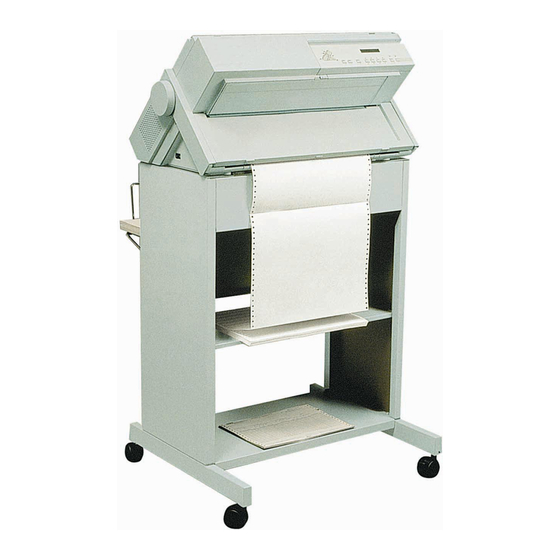
The product is composed of: - Color motor - User Manual 1.3.2.5 Pedestal 1A3003B05 Marketing Identifier: The product is composed of: - Inclinable two levels floor pedestal (for document on demand application) - Installation Manual GENICOM 3460 / 3480 / 3480+ 1.13 GEK-89537... -
Page 27: Prnters Technical Specifications
Dot Graphic Mode: 2100 2100 2100 1660 2100 1245 2100 2100 2100 2100 2100 2100 2100 2100 ### THROUGHPUT PPH ECMA 132 PPH= pages per hour Model 3460 Model 3480/80+ Fanfold ASF Fanfold ASF GENICOM 3460 / 3480 / 3480+ 1.14 GEK-89537... - Page 28 Maintenance Manual General Overview Letter Draft: Letter Quality: Graphic: Spread 17: Spead 10: GENICOM 3460 / 3480 / 3480+ 1.15 GEK-89537...
-
Page 29: Character Pitch
### BIT IMAGE (DOT GRAPHICS) Model 3460 Model 3480/80+ Horizontal: 60, 72, 120, 144 60, 80, 90, 120, 216, 240, 288 180, 240, 360 Vertical: 60, 72, 144, 216 60, 72, 144, 180 GENICOM 3460 / 3480 / 3480+ 1.16 GEK-89537... - Page 30 Maintenance Manual General Overview GENICOM 3460 / 3480 / 3480+ 1.17 GEK-89537...
-
Page 31: Character Sets
12 BAR-CODE types: UPC-A, UPC-E, EAN8, EAN 13, 2/5 INTERLEAVED CODE 3 of 9, CODE 93, CODABAR, CODE 128, POSTNET, CODE 11, MSI Height, Check Digit, Horizontal Print density programmable. Human Readable Characters available. GENICOM 3460 / 3480 / 3480+ 1.18 GEK-89537... - Page 32 1 + 7 WEIGHT (original) minimum 55 gr/M² 13.75 lbs maximum 150 gr/M² 37.5 lbs WEIGHT (Multicopy) copies minimum 45 gr/M² 11.25 lbs maximum 75 gr/M² 18.75 lbs carbon maximum 35 gr/M² 8.75 lbs GENICOM 3460 / 3480 / 3480+ 1.19 GEK-89537...
- Page 33 Maintenance Manual General Overview REAR PULL FANFOLD Frontal pull fanfold feeding and straight path Same as Front Push Fanfold GENICOM 3460 / 3480 / 3480+ 1.20 GEK-89537...
- Page 34 40 gr/M² 10.0 lbs maximum 60 gr/M² 15.0 lbs ENVELOPES Capacity of 30 envelopes max., Size US 6, US 10 ASF 1 BIN LENGTH minimum 114 mm 4.5" ASF 2 BIN GENICOM 3460 / 3480 / 3480+ 1.21 GEK-89537...
-
Page 35: Device Protocols
5% RH to 90% RH (not condensing) The operating environment is : Temperature Range + 10 °C to + 40 °C (41 °F to 104 °F) Humidity Range 20% RH to 80% RH (not condensing) GENICOM 3460 / 3480 / 3480+ 1.22 GEK-89537... - Page 36 Overview Additional resctrictions are introduced by the paper. The ECMA standard suggestions are : Temperature Range + 16 °C to + 24 °C Humidity Range 40% RH to 60% RH (not condensing) GENICOM 3460 / 3480 / 3480+ 1.23 GEK-89537...
-
Page 37: Conformity To Standards
For these printers it is 10.000 HRS @ 25 % D.C. (excluding print head). Duty cycle rate estimated for this printer is calculated as follows: Paper Movement & Print Time Duty Cycle = ---------------------------------------------------- = 25 % Power-on Time GENICOM 3460 / 3480 / 3480+ 1.24 GEK-89537... - Page 38 Maintenance Manual General Overview Reference usage of 25% duty-cycle is assumed on the basis of the following parameters : 60% column density, 50% line density, 40% character density, 40 hours/week. GENICOM 3460 / 3480 / 3480+ 1.25 GEK-89537...
-
Page 39: User Interface
1.4 with the following: - 1 LCD Display with 16 alpha-numeric digit - 9 Push Buttons - 8 LED indicators (3 for status and 5 for paper paths) Fig. 1.4 Operator Panel Overview GENICOM 3460 / 3480 / 3480+ 1.26 GEK-89537... -
Page 40: Chapter 2 Paper Handling Overview
Maintenance Manual Paper Handling Overview Chapter 2 Paper Handling Overview GENICOM 3460 / 3480 / 3480+ GEK-89537... -
Page 41: Introduction
REAR PULL mode (PATH 4) with tractor group in position C, with input from the bottom (PATH 5), also overlapped with single sheet (PATH 1) exclusive with fanfold in PATH 3. For the first two paths, the continuous module exits from PATH 10. GENICOM 3460 / 3480 / 3480+ GEK-89537... -
Page 42: Paper Handling
On the table 2.1 it is possible to find the Paper Path Types that can be selected according to the printer Path Configurations. GENICOM 3460 / 3480 / 3480+ GEK-89537... - Page 43 FRONT & REAR PUSH+ASF2 FRONT & REAR PUSH+ASF3 A= FRONT PUSH PATH B= MANUAL PUSH PATH C= REAR PUSH PATH D= REAR PULL PATH E= PUSH-PULL PATH F= ASF 1 G= ASF 2&3 GENICOM 3460 / 3480 / 3480+ GEK-89537...
-
Page 44: Paper Feeder Movements
(9) to the sector gear (16). At this point, a paper movement slides the the friction bar assy with the sector gear splined to its shaft (16) to the proper open or closed position. GENICOM 3460 / 3480 / 3480+ GEK-89537... - Page 45 Maintenance Manual Paper Handling Overview GENICOM 3460 / 3480 / 3480+ GEK-89537...
- Page 46 Maintenance Manual Paper Handling Overview Figure 2.2 Paper Feeder Parts on Right Side GENICOM 3460 / 3480 / 3480+ GEK-89537...
- Page 47 . If any intervention of this kind has been done, it is indispensable to run the T&D to assure the correct correspondance. Figure 2.4 Automatic Movement of Friction Rollers GENICOM 3460 / 3480 / 3480+ GEK-89537...
-
Page 48: Paper Path Configurations
The bail assy must be lifted (upper position) and the selection slider located on the left side of the printer must be in its up position to assure the correct rotation of the rear tractor (see chapter 2.2.5 or user manual for major details). GENICOM 3460 / 3480 / 3480+ GEK-89537... - Page 49 Maintenance Manual Paper Handling Overview Figure 2.5 Front Load Push-Mode Figure 2.6 Rear Load Push-Mode GENICOM 3460 / 3480 / 3480+ 2.10 GEK-89537...
-
Page 50: Dual Fanfold Configurations
The bail assy must be lifted (upper position) and the selection slider located on the left side of the printer must be in its up position to assure the correct rotation of the rear tractor. GENICOM 3460 / 3480 / 3480+ 2.11 GEK-89537... - Page 51 Maintenance Manual Paper Handling Overview Figure 2.8 Front Load Push-Mode and Rear Load Push-Mode with two tractors GENICOM 3460 / 3480 / 3480+ 2.12 GEK-89537...
- Page 52 Maintenance Manual Paper Handling Overview Figure 2.9 Front Load Push-Pull Mode with two tractors GENICOM 3460 / 3480 / 3480+ 2.13 GEK-89537...
-
Page 53: Asf Configuration
The figure 2.10 on next page shows the positions of the Automatic Sheet Feeder and related paper paths. The ASF can co-exists with both the push-pull tractor units (front and rear) installed. The 1st BIN can accept also envelopes. Figure 2.10 Automatic Sheet Feeder GENICOM 3460 / 3480 / 3480+ 2.14 GEK-89537... -
Page 54: Actions To Put Rear Tractor In Pull Mode
The figure 2.11 shows the manual actions that must be done to put the rear tractor unit in PULL mode instead of push. ### Check that the plastic slider is in "PULL" mode selection (up position). ### Open the top cover and gently lift the paper bail assy. GENICOM 3460 / 3480 / 3480+ 2.15 GEK-89537... - Page 55 Maintenance Manual Paper Handling Overview Figure 2.11 Actions to do to put the Rear Tractor in Pull mode GENICOM 3460 / 3480 / 3480+ 2.16 GEK-89537...
-
Page 56: Chapter 3 Removal And Replacement
Maintenance Manual Removal and Replacement Chapter 3 Removal and Replacement for 3460 (A2) / 3480 (A2) GENICOM 3460 / 3480 / 3480+ GEK-89537... -
Page 57: Overview
Serial 232 Loop-Back Connector P.N. 78403675-001 Serial 422 Loop-Back Connector P.N. 78403676-001 Parallel Loop-Back Connector P.N. 78401829-001 Mechanical Option Loop-Back Connector P.N. 78403674-001 ### Antistatic Tools (on-site) P.N. 76166990-209 Antistatic Tools (repair bech) P.N. 76957474-002 GENICOM 3460 / 3480 / 3480+ GEK-89537... -
Page 58: Serial Interface Board
Table 3-1 ORU ORDER OF ACCESS NOTE : Procedure with an asterisk require ADJUSTMENT PROCEDURE (see chapter 5) All the spare parts available on logistic are reported in the specific Illustrated Parts Catalog at chapter GENICOM 3460 / 3480 / 3480+ GEK-89537... - Page 59 4) Remove the push-pull tractor unit by pulling it downward. Replace the tractor group following the above instructions in reverse order. The same operations are required for the optional rear push-pull tractor group. GENICOM 3460 / 3480 / 3480+ GEK-89537...
- Page 60 Maintenance Manual Removal and Replacement Figure 3.1 Push-Pull Front Tractor Group removal GENICOM 3460 / 3480 / 3480+ GEK-89537...
-
Page 61: Operator Panel Boards
7) Remove the operator panel board from the LCD display board by acting on the two plastic spacers catches that retain the boards together. Replace the operator panel boards group following the above instructions in reverse order. GENICOM 3460 / 3480 / 3480+ GEK-89537... - Page 62 Maintenance Manual Removal and Replacement Figure 3.2 Operator Panel Parts removal GENICOM 3460 / 3480 / 3480+ GEK-89537...
-
Page 63: Print Head
6) Remove the printhead. Replace the Print Head following the above instructions in reverse order. NOTICE : Before securing the screw, push the P.H. to its inside stop position. No adjustment is required. GENICOM 3460 / 3480 / 3480+ GEK-89537... - Page 64 Maintenance Manual Removal and Replacement Figure 3.3 Printhead Removal GENICOM 3460 / 3480 / 3480+ GEK-89537...
-
Page 65: Front Cover Parts
6) Extract the magnet interlock from the front cover by simply pulling it out of the cover. Replace the Main Front Cover Parts following the above instructions in reverse order. Figure 3.4 Main Front Cover Parts GENICOM 3460 / 3480 / 3480+ 3.10 GEK-89537... -
Page 66: Rear Cover Parts
8) Extract the paper knob by simply pulling it out from the platen axis. Replace the Main Rear Cover Parts following the above instructions in reverse order. Figure 3.5 Main Rear Cover Parts GENICOM 3460 / 3480 / 3480+ 3.11 GEK-89537... -
Page 67: Serial Interface
2) Unscrew the two screws securing the serial interface board to the base assy. 3) Remove the the Serial Interface Board by simply extracting it from the main board connector. Figure 3.6 Serial Interface Board GENICOM 3460 / 3480 / 3480+ 3.12 GEK-89537... -
Page 68: Main Board
7) Unscrew the two screws fixing the metal plate on the parallel connector and remove it. Replace the Main Rear Cover Parts following the above instructions in reverse order paying attention to the rear horizontal guides and to its bottom shield. GENICOM 3460 / 3480 / 3480+ 3.13 GEK-89537... - Page 69 Maintenance Manual Removal and Replacement Figure 3.7 Main Board GENICOM 3460 / 3480 / 3480+ 3.14 GEK-89537...
-
Page 70: Power Supply Board
6) Unplug the connector from the main board and gently extract the power supply board from the printer. Replace the power supply board following the above instructions in reverse order paying attention to the rear horizontal guides. GENICOM 3460 / 3480 / 3480+ 3.15 GEK-89537... - Page 71 Maintenance Manual Removal and Replacement Figure 3.8 Power Supply Board GENICOM 3460 / 3480 / 3480+ 3.16 GEK-89537...
-
Page 72: Ribbon Motor
7) Remove the pivot assy. Replace the ribbon motor assy and the left support parts following above instructions in reverse order. GENICOM 3460 / 3480 / 3480+ 3.17 GEK-89537... - Page 73 Maintenance Manual Removal and Replacement Figure 3.9 Ribbon Motor and left cartridge support GENICOM 3460 / 3480 / 3480+ 3.18 GEK-89537...
-
Page 74: Aga Motor
Replace the AGA motor following the above instructions in reverse order. NOTICE : Before tighteing the motor screws, verify the correct and free movement of the AGA gears. Run the AGA calibration procedure to verify the correct AGA marker position. GENICOM 3460 / 3480 / 3480+ 3.19 GEK-89537... - Page 75 Maintenance Manual Removal and Replacement Figure 3.10 AGA Motor GENICOM 3460 / 3480 / 3480+ 3.20 GEK-89537...
-
Page 76: Aga Support And T/F Lever
Replace the AGA support and T/F lever following the above instructions in reverse order. NOTICE: Put the AGA marker position in the same previous position. Run the AGA calibration procedure to verify the correct AGA marker position. GENICOM 3460 / 3480 / 3480+ 3.21 GEK-89537... - Page 77 Maintenance Manual Removal and Replacement Figure 3.11 Aga Support and T/F Lever GENICOM 3460 / 3480 / 3480+ 3.22 GEK-89537...
-
Page 78: Carriage Motor
12) Remove the carriage motor assy. Replace the carriage motor assy following the above instructions in reverse order. NOTICE : The carriage motor replacement requires an appropriate carriage belt adjustment (refer to chapter 5). GENICOM 3460 / 3480 / 3480+ 3.23 GEK-89537... - Page 79 Maintenance Manual Removal and Replacement Figure 3.12 Carriage Motor GENICOM 3460 / 3480 / 3480+ 3.24 GEK-89537...
-
Page 80: Bail Assy
3) Rotate the bail assy toward its front side to unhook it from the left and right mechanical frames. 4) Remove the bail assy. Replace the bail assy following the above instructions in reverse order. Figure 3.13 Bail Assembly GENICOM 3460 / 3480 / 3480+ 3.25 GEK-89537... -
Page 81: Cut Sheet Assy
3) Gently remove the cut sheet assy by simply extracting it from the mechanical assy from the left side. Replace the cut sheet assy following the above instructions in reverse order. Figure 3.14 Cut Sheet Assembly GENICOM 3460 / 3480 / 3480+ 3.26 GEK-89537... -
Page 82: Upper Feeder Assy
7) Remove the upper feeder assy by extracting it from the left side of the mechanical assy rotating the feeder assy on the left side slightly to the front. Replace the upper feeder assy following the above instructions in reverse order. Figure 3.15 Upper Feeder Assy GENICOM 3460 / 3480 / 3480+ 3.27 GEK-89537... -
Page 83: Platen Assy
8) Gently shift the platen assy left from its position and then extract it from the left side of the mechanical assy. Replace the platen assy following the above instructions in reverse order. NOTICE: the platen assy replacement requires an appropriate print head gap adjustment procedure (refer to chapter 5). GENICOM 3460 / 3480 / 3480+ 3.28 GEK-89537... - Page 84 Maintenance Manual Removal and Replacement Figure 3.16 Platen Assy GENICOM 3460 / 3480 / 3480+ 3.29 GEK-89537...
-
Page 85: Lower Feeder Assy
Replace the lower feeder assy following the above instructions in reverse order. NOTICE : the lower feeder assy replacement requires an appropriate carriage and paper belts adjustment procedure (refer to chapter 5). GENICOM 3460 / 3480 / 3480+ 3.30 GEK-89537... - Page 86 Maintenance Manual Removal and Replacement Figure 3.17 Lower Feeder Assy GENICOM 3460 / 3480 / 3480+ 3.31 GEK-89537...
-
Page 87: Carriage Assy
NOTICE: the carriage assy replacement requires the appropriate print head gap and carriage belt adjustment procedures (refer to chapter 5). Slowly introduce the front bar into the carriage holes paying attention to the oil-felt inside it. Figure 3.18 Carriage Assy GENICOM 3460 / 3480 / 3480+ 3.32 GEK-89537... -
Page 88: Sensor Assy
10) Unplug the connector from the main board and extract the cable from its cable retainers located in the rear part of the mechanical assy. Replace the sensor assy following the above instructions in reverse order. GENICOM 3460 / 3480 / 3480+ 3.33 GEK-89537... -
Page 89: Sensor Assy
Maintenance Manual Removal and Replacement Figure 3.19 Sensor Assy GENICOM 3460 / 3480 / 3480+ 3.34 GEK-89537... -
Page 90: Mechanical Assy
5) Cut the two plastic self-locked strips retaining the mechanical blocks on the base assy and remove the mechanical assy. 6) Pay attention to the paper position mylar on the base assy. Replace the mechanical assy following the above instructions in reverse order. GENICOM 3460 / 3480 / 3480+ 3.35 GEK-89537... - Page 91 Maintenance Manual Removal and Replacement Figure 3.20 Mechanical Assy GENICOM 3460 / 3480 / 3480+ 3.36 GEK-89537...
-
Page 92: Paper Motor Assy
Replace the paper motor following the above instructions in reverse order. NOTICE: the paper motor replacement requires an appropriate paper belt adjustment procedure (refer to chapter 5). Figure 3.21 Paper Motor GENICOM 3460 / 3480 / 3480+ 3.37 GEK-89537... -
Page 93: Friction Bar Assy
Replace the friction bar assy following the above instructions in reverse order. NOTICE: the friction bar assy must have a proper position coherently with the sensor tuning values stored in NVM. See chapter 6.4 for more details. Figure 3.22 Friction Bar Assy GENICOM 3460 / 3480 / 3480+ 3.38 GEK-89537... - Page 94 Maintenance Manual Removal and Replacement Chapter 4 Removal and Replacement for 3460 (A3) / 3480 (A3) / 3480+ GENICOM 3460 / 3480 / 3480+ GEK-89537...
- Page 95 Table 4-1 ORU ORDER OF ACCESS NOTE : Procedure with an asterisk require ADJUSTMENT PROCEDURE (see next chapter) All the spare parts available on logistic are reported in the specific Illustrated Parts Catalog. GENICOM 3460 / 3480 / 3480+ GEK-89537...
-
Page 96: Operator Panel Board
Run the AGA calibration procedure (T&D 12) to verify a correct AGA value. 4.3.4 Front Cover Parts See the same section of the chapter 3. 4.3.5 Rear Cover Parts See the same section of the chapter 3. GENICOM 3460 / 3480 / 3480+ GEK-89537... - Page 97 S3= Generator firmware location. MODEL RELEASE CODE I.C. TYPE LOCATION CHECKSUM XXXX (controller) 3480+ XXXX (T&D) XXXX (generator) XXXX (controller) 3480 (A3) XXXX (T&D) XXXX (generator) XXXX (controller) 3460 (A3) XXXX (T&D) XXXX (generator) GENICOM 3460 / 3480 / 3480+ GEK-89537...
- Page 98 4.3.13 Cut Sheet Assy See the related section of the chapter 3. 4.3.14 Upper Feeder Assy See the related section of the chapter 3. 4.3.15 Platen Assy See the related section of the chapter 3. GENICOM 3460 / 3480 / 3480+ GEK-89537...
- Page 99 Maintenance Manual Removal and Replacement Figure 4.3 Force for fixing platen and main shaft of carriage assy GENICOM 3460 / 3480 / 3480+ GEK-89537...
- Page 100 4.15B (force F2), then secure in sequence the screws C and D. Check for the correct tighten of the belt clamp screw securing the carriage belt. NOTICE: the carriage assy replacement requires the appropriate print head gap and carriage belt adjustment procedures. GENICOM 3460 / 3480 / 3480+ GEK-89537...
- Page 101 Maintenance Manual Removal and Replacement Figure 4.4 Carriage Assy GENICOM 3460 / 3480 / 3480+ GEK-89537...
-
Page 102: Friction Bar Assy
4) Gently remove the ribbon mask. Replace the ribbon mask following the above instructions in reverse order. rib. mask ---> screw A ---> <--- screw B print head Figure 4.6 Ribbon mask removal (top view) GENICOM 3460 / 3480 / 3480+ GEK-89537... - Page 103 Replace the lower mylar following the above instructions in reverse order. Figure 4.7 Support spring with lower mylar 1- Support spring 2- Lower mylar 3- Screws fixing lower mylar with the support spring GENICOM 3460 / 3480 / 3480+ 4.10 GEK-89537...
- Page 104 Maintenance Manual Adjustments Chapter 5 Adjustments GENICOM 3460 / 3480 / 3480+ GEK-89537...
-
Page 105: Carriage Belt
5) Keep the screw fixed and, at the same time, tighten the nut. After this adjustment it is necessary to run the bidirectional printing adjustment to assure the best performances of the printer. GENICOM 3460 / 3480 / 3480+ GEK-89537... - Page 106 Maintenance Manual Adjustments F=0.7Kg Figure 5.1 Carriage Assy Belt Adjustment GENICOM 3460 / 3480 / 3480+ GEK-89537...
-
Page 107: Maintenance
An hole on the base assy is provided for this purpose. After this adjustment it is necessary to run the T&D procedures to verify the correct forward - backward paper advancing in fanfold and single sheet paper. GENICOM 3460 / 3480 / 3480+ GEK-89537... - Page 108 Maintenance Manual Adjustments Figure 5.2 Paper Belt Adjustment GENICOM 3460 / 3480 / 3480+ GEK-89537...
-
Page 109: Print Head Gap
. If only the platen assy has been replaced with a new one, it is possible GENICOM 3460 / 3480 / 3480+ GEK-89537... - Page 110 In case the alignment is not correct (>0.08mm) follows these steps: If the white dot is painted on the eccentric bushing: 7a) Verify if the white dot on the rear bar eccentric bushing matches with the one located on the right side. GENICOM 3460 / 3480 / 3480+ GEK-89537...
- Page 111 AGA marker has the minimum value and paints the red dot on its left axe for future use. 12) Store the correct AGA value and power off the printer. GENICOM 3460 / 3480 / 3480+ GEK-89537...
- Page 112 Maintenance Manual Adjustments Figure 5.3 Print Head Adjustment Figure 5.4 AGA Marker Adjustment 5.1.4 AGA Calibrate GENICOM 3460 / 3480 / 3480+ GEK-89537...
- Page 113 AGA value. means a negative change of the AGA value (PAPER ⇓ key) The range of the variation is from -8 to +8 (every unit changes the gap of 0.03 mm). GENICOM 3460 / 3480 / 3480+ 5.10 GEK-89537...
-
Page 114: Form Thickness
FORM: FIXED>0.6 - Press ENTER key, the display shows: - Use the ⇓ key to select the proper value in the range between 0.3 to 8.6. - Press ENTER key to save selection. GENICOM 3460 / 3480 / 3480+ 5.11 GEK-89537... - Page 115 FRONT or REAR value (PAPER ⇓ key) The range of the variation is from -128 to +127 (every unit is the minimum paper motor movement = 1/144" for 9 needles model and 1/180" for 24 needles model). GENICOM 3460 / 3480 / 3480+ 5.12 GEK-89537...
- Page 116 If the LF key is pressed, the FRONT or REAR calibration procedure is executed again (a printout of eight "EEEEEEEE" shifted on the right side of the previous one is done) and the display shows "YES<- STORE ->NO". GENICOM 3460 / 3480 / 3480+ 5.13 GEK-89537...
-
Page 117: Page Setup
- Press ENTER key to save selection. The range is between -90/90 to +180/90 inch or -1 to -2 inches for 3480 model or between 72/72 to +144/72 inch for 3460 model depending upon the SYSTEM MENU (PROGRAM UNITS). 5.1.6 Vertical (bidirectional printing) This adjustment is required only if some parts related to the carriage assy movement are removed. - Page 118 Maintenance Manual Adjustments If YES is choosen for one of the previous tests, the procedure runs. The display will show "VERTICAL ADJUST". GENICOM 3460 / 3480 / 3480+ 5.15 GEK-89537...
- Page 119 HHHHHHHHHH HHHHHHHHHH HHHHHHHHHH H HHHHHHHHH HHHHHHHHHH HHHHHHHHHH HHHHHHHHHH HHHHHHHHHH HHHHHHHHHH HHHHHHHHHH HHHHHHHHHHHHHHHHHHHHHHHHHHHHHHHHHHHHHHHHHHHHHHHHHHHHHHHHHHHHHHHHHHHHHHHHHHHHHHHHHHHHHHHHHHHHHHHHHHHHHHHHHHHH HHHHHHHHHH HHHHHHHHHH HHHHHHHHHH HHHHHHHHHH HHHHHHHHHH HHHHHHHHHH HHHHHHHHHH HHHHHHHHHH HHHHHHHHHH HHHHHHHHHH HHHHHHHHHH HHHHHHHHHH H HHHHHHHHH HHHHHHHHHH HHHHHHHHHH HHHHHHHHHH HHHHHHHHHH HHHHHHHHHH HHHHHHHHHH HHHHHHHHHHHHHHHHHHHHHHHHHHHHHHHHHHHHHHHHHHHHHHHHHHHHHHHHHHHHHHHHHHHHHHHHHHHHHHHHHHHHHHHHHHHHHHHHHHHHHHHHHHHH GENICOM 3460 / 3480 / 3480+ 5.16 GEK-89537...
-
Page 120: Tear-Off Line
If the LF key is pressed, the TEAR calibration procedure is executed again (no further printout is done) and the display shows "YES <- STORE-> NO". means the store in NVM of the selected value (LOAD/FF key) and skip to next test (T&D 18). GENICOM 3460 / 3480 / 3480+ 5.17 GEK-89537... - Page 121 Maintenance Manual Adjustments means that this test will be repeated (PAPER ⇓ key). GENICOM 3460 / 3480 / 3480+ 5.18 GEK-89537...
- Page 122 ALWAYS WITHOUT ANY PAPER INSERTED IN ALL PATHS. ### At FIELD level, the test is automatically executed in the T&D 11 test (this is the first test of the mechanism). ### At USER level in the INITIAL SET-UP Menu. GENICOM 3460 / 3480 / 3480+ 5.19 GEK-89537...
- Page 123 Maintenance Manual Adjustments GENICOM 3460 / 3480 / 3480+ 5.20 GEK-89537...
-
Page 124: Sensor Tune
SENSOR TUNE - Press the ENTER key to select this function. TUNE>N The display shows: - Use the ⇓ key to select YES value. TUNE>Y - Press ENTER key to save selection. GENICOM 3460 / 3480 / 3480+ 5.21 GEK-89537... - Page 125 Maintenance Manual Service Maintenance Chapter 6 Service Maintenance GENICOM 3460 / 3480 / 3480+ GEK- 89537...
-
Page 126: General Remark
Test & Diagnostic facilities. For all other aspects regarding the printers setting and printer programming, please refer to the following manuals: • Model 3460/3480 User's manual (P.N. GEK-89170) • Model 3460 Programmer's manuals (P.N. GEK-89212) •... -
Page 127: Paper Specifications
See chapter 1.3 and the USER manual for more details. 6.2.4 Consumables Genicom reccomends to use only its original consumables with original packaging. In this way, a proper use of the printer at the quality level and reliability stated in the product characteristics can be assured. - Page 128 Maintenance Manual Service Maintenance ### other standard GENICOM 3460 / 3480 / 3480+ GEK- 89537...
-
Page 129: Troubleshooting Guide
6.3.2 Printer Errors Some errors can be displayed by the printer. These errors can be divided into three main groups: ### Status errors ### Recoverable errors ### Not recoverable errors 6.3.2.1 Status Errors GENICOM 3460 / 3480 / 3480+ GEK- 89537... - Page 130 When an error of this kind occurs, the printer shows some messages to the User with the action to do to fix or by-pass the error condition. See 3460 and 3480 Models User manuals for major details. GENICOM 3460 / 3480 / 3480+...
-
Page 131: Recoverable Errors
The host is sending data to the printer even if it has been required to stop transmission. Action: Check the connection between the printer and the host. Press the ON LINE key to reset the error condition. Turn the printer off if the buffer must be cleared. GENICOM 3460 / 3480 / 3480+ GEK- 89537... - Page 132 Cause: The eprom of the basic FW on the main board has been changed (for FW updating) or the main board has been replaced with a new one. Action: Push any key to Initialize. All the Menu Items are set to their default values. GENICOM 3460 / 3480 / 3480+ GEK- 89537...
-
Page 133: Unrecoverable Errors
Table 6.1A Unrecoverable Error Display Messages (Boostrap Phase) In the normal operation phase a unrecoverable message with a combination of the following parameters can be displayed. DEVICE (SPV, INT, P_M, ENG) SERVO (n1) CODE (n2) GENICOM 3460 / 3480 / 3480+ GEK- 89537... - Page 134 Maintenance Manual Service Maintenance COMMAND (n3) ENG FLT 4 3 0 Means an Engine Device Initialization failure error. Example: GENICOM 3460 / 3480 / 3480+ 6.10 GEK- 89537...
-
Page 135: Error Description
EPROMs or by the microcontroller or by the data bus problems (Eproms or Main Board F.R.U.). For the last two ENGINE errors see the faulty probability guide in chapter 6.3.6. GENICOM 3460 / 3480 / 3480+ 6.11 GEK-... -
Page 136: Power Malfunctions
1) Insert the hole present in the rear part of the Power Suppy cover tool into the plastic pin located on the base assy. 2) Hook the front part of the cover to the base assy. GENICOM 3460 / 3480 / 3480+ 6.12 GEK-... -
Page 137: Power Supply Cover Tool Installation
+5v. If the fuses blown again, replace the power supply board. ### The printer is powered off after a short time power on. Cause: An overload is present on secondary voltages. GENICOM 3460 / 3480 / 3480+ 6.13 GEK- 89537... - Page 138 + 38 V DC CONNECTOR PIN 9 + 38 V DC CONNECTOR PIN 10 + 38 V DC CONNECTOR PIN 11 (a) + 79 V DC CONNECTOR PIN 12 FAN CONTROL (not used) GENICOM 3460 / 3480 / 3480+ 6.14 GEK- 89537...
- Page 139 Maintenance Manual Service Maintenance Figure 6.2 Power Supply Test Points GENICOM 3460 / 3480 / 3480+ 6.15 GEK- 89537...
- Page 140 Refer to the faulty probability table to correct any printing problem. GENICOM 3480 Matrix Advantage CONTROLLER : 78404534 Rel: 2.06 44A513937-G20 GENERATOR 78403830 Rel: 1.03 44A513937-G50 FONT :COURIER EMULATION :EPSON LQ !"#$%&'()*+,-./0123456789:;<=>?@ABCDEFGHIJKLMNOPQRSTUVWXYZ[\]^_ab !"#$%&'()*+,-./0123456789:;<=>?@ABCDEFGHIJKLMNOPQRSTUVWXYZ[\]^_abc GENICOM 3460 / 3480 / 3480+ 6.16 GEK- 89537...
- Page 141 Maintenance Manual Service Maintenance "#$%&'()*+,-./0123456789:;<=>?@ABCDEFGHIJKLMNOPQRSTUVWXYZ[\]^_abcd Figure 6.3 Self-Test Printout GENICOM 3460 / 3480 / 3480+ 6.17 GEK- 89537...
-
Page 142: Test Mode
0002 0A 42 41 53 49 43 3A 20 43 48 52 24 28 32 37 29 0003 3B 43 48 52 24 28 36 37 29 3B 43 48 52 24 28 37 ;CHR$(67);CHR$(7 0004 32 29 0D 0A 2)W¤ Figure 6.4 Hex-Dump Printout GENICOM 3460 / 3480 / 3480+ 6.18 GEK- 89537... - Page 143 The power supply board may be faulty. ACTION: Check the voltages. Install a new one. CAUSE: The gap between P.H. and platen is not correct. ACTION: Check for the platen adjustment procedure. GENICOM 3460 / 3480 / 3480+ 6.19 GEK- 89537...
- Page 144 The connection of the motor and main board is defective. ACTION: Verify the connection. Replace the cable. CAUSE: The main board may be faulty. ACTION: Install a new one. Run T&D procedure to verify. GENICOM 3460 / 3480 / 3480+ 6.20 GEK- 89537...
- Page 145 CAUSE: The connections of the home position sensor or the carriage motor are defective. ACTION: Verify the connections of the sensors cable group and carriage motor on main board. GENICOM 3460 / 3480 / 3480+ 6.21 GEK- 89537...
- Page 146 The home position sensor or the carriage motor assy are faulty. ACTION: Check for the sensor action through the carriage assy and the motor impedance. Replace the sensors cable group or the carriage motor assy. GENICOM 3460 / 3480 / 3480+ 6.22 GEK- 89537...
- Page 147 The home position sensor detects a carriage stop. ACTION: First check the carriage for its proper free movement. Check the carriage belt correct mounting. Check the sensors cable proper connection to the main board. Check the main board GENICOM 3460 / 3480 / 3480+ 6.23 GEK- 89537...
-
Page 148: Test & Diagnostic
Together with this card three loop-back must be installed: The 232 serial loop-back connector P.N. 78403675-001 The 422 serial loop-back connector P.N. 78403676-001 The mechanical options loop-back connector P.N. 78403674-001 The parallel loop-back connector P.N. 78401829-001 GENICOM 3460 / 3480 / 3480+ 6.24 GEK- 89537... - Page 149 In fact, the T&D automatically adjusts, whitout any intervention, all the reflective sensors of the printer (single sheet, front fanfold, rear fanfold). ### The cover must be closed, otherwise a message "# COVER OPEN " will be displayed. GENICOM 3460 / 3480 / 3480+ 6.25 GEK- 89537...
-
Page 150: Loop-Back Connectors
( 3) RXD 232 Figure 6.5A 232/C Serial I/F Loop-Back Diagram 422/A SERIAL INTERFACE LOOP-BACK (20) ------------------ ( 6) DSR ( 4) ------------------ ( 5) CTS SRTS (11) ------------------ ( 8) DCD GENICOM 3460 / 3480 / 3480+ 6.26 GEK- 89537... - Page 151 Maintenance Manual Service Maintenance TX-A 422 (13) ------------------ (16) RX-A 422 TX-B 422 (14) ------------------ (19) RX-B 422 Figure 6.5B 422/A Serial I/F Loop-Back Diagram GENICOM 3460 / 3480 / 3480+ 6.27 GEK- 89537...
-
Page 152: Mechanical Option Loop-Back Diagram
Maintenance Manual Service Maintenance PARALLEL INTERFACE LOOP-BACK Figure 6.6 Parallel I/F Loop-Back Diagrams MECHANICAL OPTIONS LOOP-BACK Figure 6.7 Mechanical Option Loop-Back Diagrams GENICOM 3460 / 3480 / 3480+ 6.28 GEK- 89537... - Page 153 The next table 6.2 shows the flowchart of the T&D procedure The T&D gives some interaction messages. An indication inside a border means a certain key pressure. An indication between double brackets as below, means a display message. "LCD MESSAGE " GENICOM 3460 / 3480 / 3480+ 6.29 GEK- 89537...
-
Page 154: Diagnostic Flow Chart
"Y CHANGE IT? N" LOAD/FF Changes NVM status and store it PAPER ⇓ Skips this control "<--- START & RUN" LOAD/FF Starts ribbon & motor color test PAPER ⇓ "STOPPING ---> “ Stops test GENICOM 3460 / 3480 / 3480+ 6.30 GEK- 89537... - Page 155 Maintenance Manual Service Maintenance Table 6.2 T&D USER Flow Chart (I) GENICOM 3460 / 3480 / 3480+ 6.31 GEK- 89537...
- Page 156 "PUSH A KEY" Executes the vertical adj. test PAPER ⇓ Decrements the vertical adj. value "YES <-STORE ->NO" LOAD/FF Stores vertical adj. value in NVM PAPER ⇓ Skips to next test GENICOM 3460 / 3480 / 3480+ 6.32 GEK- 89537...
- Page 157 Maintenance Manual Service Maintenance Table 6.2 T&D USER Flow Chart cont'd (II) GENICOM 3460 / 3480 / 3480+ 6.33 GEK- 89537...
- Page 158 "T&D 18 USER" Interlock test "T&D 19 USER" "OPEN COVER" "CLOSE COVER" Friction NVM recall "FRICTION OPEN" or ANY KEY "FRICTION CLOSED" "END T&D .." Table 6.2 T&D USER Flow Chart cont'd (III) GENICOM 3460 / 3480 / 3480+ 6.34 GEK- 89537...
- Page 159 Maintenance Manual Service Maintenance On 3480+ and 3460 / 3480 A3 profile is also available the following T&D. Paper Sensors Test “T&D 20 USER” “Y SENSOR TUNE N” LOAD/FF “Y PATH STATUS N” LOAD/FF “C:F P:OP” Visual check for change F (free) to “C:B...
- Page 160 Maintenance Manual Service Maintenance SKIP means the failed test can be skipped (LF key). INIT means the T&D restarts from the beginning except the BOOT test (PAPER ⇑ key). GENICOM 3460 / 3480 / 3480+ 6.36 GEK- 89537...
-
Page 161: Vertical Adjustment Test
The table below shows the list of O.R.U (optimum replaceable unt) involved in the diagnostic phase. O.R.U. DESCRIPTION ------------------------------------------------------------------------ Main Board Operator Panel Board Diagnostic Card Mechanical Parts Supervisor SW Eproms GENICOM 3460 / 3480 / 3480+ 6.37 GEK- 89537... - Page 162 Maintenance Manual Service Maintenance Table 6.4 ORU List Table GENICOM 3460 / 3480 / 3480+ 6.38 GEK- 89537...
-
Page 163: Error Code Description
(carriage motor, paper motor) is requested (T&D 11, T&D 12, T&D 14, T&D 15, T&D 16, T&D 17, T&D 18). GENICOM 3460 / 3480 / 3480+ 6.39 GEK-... - Page 164 After that, the test checks all the 8 leds of the printer. All these leds are lit and then off, then sequentially from right to left one led is lit for about 0.5 second with an associated buzzer sound. GENICOM 3460 / 3480 / 3480+ 6.40 GEK-...
- Page 165 The last test is to verify and change, if necessary, the coherence between the internal NVM data for the Friction Bar Position and the relative mechanical position of the bar itself. As described in chapter 2, in this printer there is an automatical movement of the friction GENICOM 3460 / 3480 / 3480+ 6.41 GEK-...
- Page 166 After having pressed the LOAD/FF key, the message "Y CHANGE IT? N" will be displayed. The choice can be Y (LOAD/FF key) to change this data and stored it or N (PAPER ⇓ key) to skip this test. GENICOM 3460 / 3480 / 3480+ 6.42 GEK-...
-
Page 167: Friction Bar Assy Position
If the LOAD/FF key is pressed, the test is executed and the ribbon motor is activated together with a motor color activation and the display shows "STOPPING ->". If the PAPER ⇓ key is pressed, the test will be stopped. GENICOM 3460 / 3480 / 3480+ 6.43 GEK-... - Page 168 The display will show "LOAD CUT SHEET" and a manual paper loading is requested. The printer automatically will load the paper without any key pressure. See specific chapter 6.4.11.2 for its analysis. GENICOM 3460 / 3480 / 3480+ 6.44 GEK-...
- Page 169 A pressure on any key is necessary to skip the test. At the end of the T&D, the display will show "END T&D ..". The printer must be powered-off. GENICOM 3460 / 3480 / 3480+ 6.45 GEK- 89537...
- Page 170 A continuous line is printed in the 50th position. See step B) of item 5. A forward paper movement is performed to reach the 72th position and a pattern as described at point 1 is printed. GENICOM 3460 / 3480 / 3480+ 6.46 GEK- 89537...
- Page 171 Maintenance Manual Service Maintenance GENICOM 3460 / 3480 / 3480+ 6.47 GEK- 89537...
- Page 172 Maintenance Manual Service Maintenance Figure 6.9 3460 T&D Standard Fanfold Printout (reduced) GENICOM 3460 / 3480 / 3480+ 6.48 GEK- 89537...
- Page 173 Maintenance Manual Service Maintenance GENICOM 3460 / 3480 / 3480+ 6.49 GEK- 89537...
- Page 174 Maintenance Manual Service Maintenance Figure 6.10 3480 T&D Standard Fanfold Printout (reduced) GENICOM 3460 / 3480 / 3480+ 6.50 GEK- 89537...
- Page 175 The position of these lines should match the lines printed with the forward movement. A final form feed to paper eject is done. A mismatch of max. 1 mm is accepteptable. GENICOM 3460 / 3480 / 3480+ 6.51 GEK- 89537...
- Page 176 Maintenance Manual Service Maintenance Figure 6.11 3460/3480 T&D Standard Single Sheet Printout (reduced) GENICOM 3460 / 3480 / 3480+ 6.52 GEK- 89537...
-
Page 177: Electromechanical Devices
Maintenance Manual Electromechanical Devices Chapter 7 Electromechanical Devices GENICOM 3460 / 3480 / 3480+ GEK-89537... -
Page 178: Electrical Requirements
7.1.1 Print Head The print head installed on this printer is an electromagnetic non-ballistic type. There are three different types, one for 3460 (9 needles), one for 3480 (24 needles) and another one for 3480+ (24 needles). For the 9 pins print head, the needles have diameter of 0.3 mm (0.012") and they are positioned in a single row with vertical pitch of 0.353 mm (1/72"). -
Page 179: Mechanical Requirements
Connector P2 Pin 1 + 38 Volt Pin23 Connector P2 Pin 4 + 38 Volt Pin24 Connector P2 Pin 3 Table 7.1 9 Needles print head pin assignment Figure 7.1 9 Needles print head pinout GENICOM 3460 / 3480 / 3480+ GEK-89537... - Page 180 Needle N. 3 Pin10 Needle N. 19 Pin21 + 38 Volt Needle N. 17 Pin22 Needle N. 1 Table 7.3 24 Needles print head pin assignment Figure 7.2 24 Needles print head pinout GENICOM 3460 / 3480 / 3480+ GEK-89537...
- Page 181 With rated current applied to both phases (series). Back electromotive force 20 Vpeak ± 20% With motor shaft at the constant speed of 1000 RPM MECHANICAL REQUIREMENTS Step angle 1.8° The pin connector assignment is shown in fig. 7.3 GENICOM 3460 / 3480 / 3480+ GEK-89537...
- Page 182 Rated phase current 1.4 A With rated current applied to both phases (series). Back electromotive force 29 Vpeak ± 20% With motor shaft at the constant speed of 1000 RPM MECHANICAL REQUIREMENTS Step angle 1.8° GENICOM 3460 / 3480 / 3480+ GEK-89537...
- Page 183 Maintenance Manual Electromechanical Devices The pin connector assignment is shown in fig. 7.4. Fig 7.4 Paper motor pin connector assignment GENICOM 3460 / 3480 / 3480+ GEK-89537...
- Page 184 15.5 Vpeak ± 20% With motor shaft at the constant speed of 1000 RPM MECHANICAL REQUIREMENTS Step angle 3.6° The pin connector assignment is shown in fig. 7.5 Fig 7.5 AGA motor pin connector assignment GENICOM 3460 / 3480 / 3480+ GEK-89537...
- Page 185 21 Vpeak ± 20% With motor shaft at the constant speed of 1000 RPM MECHANICAL REQUIREMENTS Step angle 7.5° The pin connector assignment is shown in fig. 7.6 Fig 7.6 Ribbon motor pin connector assignment GENICOM 3460 / 3480 / 3480+ GEK-89537...
-
Page 186: Asf Motor
The Stall current is the armature current when the rated motor voltage is applied to the motor with locked rotor. No load current 0.038 A ± 40% The No load current is the motor armature supply current at no load speed. GENICOM 3460 / 3480 / 3480+ 7.10 GEK-89537... - Page 187 With rated current applied to both phases (series). MECHANICAL REQUIREMENTS Travel 18 mm Incremental unit 0.0846 mm ± 10% The pin connector assignment is shown in fig. 7.7 Fig 7.7 Color motor pin connector assignment GENICOM 3460 / 3480 / 3480+ 7.11 GEK-89537...
-
Page 188: Stacker Motor
With rated current applied to both phases (series). Back electromotive force 17.5 Vpeak ± 20% With motor shaft at the constant speed of 1000 RPM MECHANICAL REQUIREMENTS Step angle 15° The pin connector assignment is shown in fig. 7.8 GENICOM 3460 / 3480 / 3480+ 7.12 GEK-89537... - Page 189 Maintenance Manual Electromechanical Devices Fig 7.8 Stacker motor pin connector assignment GENICOM 3460 / 3480 / 3480+ 7.13 GEK-89537...
- Page 190 7.1.3 Cables 7.1.3.1 Sensors Cable This cable is composed of five optical sensors (two interrupter and three reflective ones). The figure below shows the electrical connections of this cable. Fig. 7.9 Sensors Cable GENICOM 3460 / 3480 / 3480+ 7.14 GEK-89537...
- Page 191 The figure below shows the electrical connections of this cable. Fig. 7.10 Alternance Cable 7.1.3.3 Paper Stacker Cable The figure below shows the electrical connections of this cable. Fig. 7.11 Paper Stacker Cable GENICOM 3460 / 3480 / 3480+ 7.15 GEK-89537...
-
Page 192: Operator Panel Cable
Maintenance Manual Electromechanical Devices 7.1.3.4 Operator Panel Cable The figure below shows the electrical connections of this cable. Fig. 7.12 Operator Panel Cable GENICOM 3460 / 3480 / 3480+ 7.16 GEK-89537... - Page 193 Maintenance Manual Interfaces Chapter 8 Interfaces GENICOM 3460 / 3480 / 3480+ GEK-89537...
-
Page 194: Ieee 1284 Parallel Interface
2) This interface provides a path for data to be sent from the peripheral device to the host using existing and future parallel port hardware. 3) The reverse channel capability reduces the amount of user interaction needed to operate the peripheral device. GENICOM 3460 / 3480 / 3480+ GEK-89537... - Page 195 For example, application program can ask a printer for a list of fonts currently available. The application can then decide if new fonts must be downloaded, rather than asking the user to do it. GENICOM 3460 / 3480 / 3480+ GEK-89537...
-
Page 196: Communication Modes
Compatibility Mode Forward Idle Phase The interface is in Compatibility mode with no data transfer in progress. The host may initiate a data transfer in Compatibility mode, or may initiate negotiation to a new operating mode. GENICOM 3460 / 3480 / 3480+ GEK-89537... - Page 197 Maintenance Manual Interfaces GENICOM 3460 / 3480 / 3480+ GEK-89537...
- Page 198 The value 00h means Nibble Mode, while the value 01h means Byte Mode The printer answer on Xflag signal to this value. The Xflag affermative response is LOW for Nibble Mode, HIGH for Byte Mode. GENICOM 3460 / 3480 / 3480+ GEK-89537...
- Page 199 Maintenance Manual Interfaces GENICOM 3460 / 3480 / 3480+ GEK-89537...
-
Page 200: Parallel Interface Signals
1284 Active (NSelectIn) Common Logic Ground 16, 33 Chassis Ground Optional output voltage (+ 5V DC) PRINTER (max. 250mA) Pulled up signal (+ 5V DC) PRINTER (3.3 KΩ pull-up) Table 8.1 Parallel Interface Pin Assignment GENICOM 3460 / 3480 / 3480+ GEK-89537... -
Page 201: Parallel Interface Signals Behaviour
(nFault). Reverse Data Transfer phase: Nibble Mode: Data bits 2 then 6. Byte Mode : Same as nDataAvail (nFault) Reverse Idle phase: Set high until host requests data transfer, then follows nDataAvail (nFault). GENICOM 3460 / 3480 / 3480+ GEK-89537... - Page 202 Then used to send data bits 0 then 4. Byte Mode : Used to indicate that data is available. Reverse Idle phase : Used to indicate that data is available. GENICOM 3460 / 3480 / 3480+ 8.10 GEK-89537...
- Page 203 Set high to indicate that bus direction is printer to host. Set low to terminate 1284 mode and set bus direction host to printer. Reverse Idle phase : Same as Reverse Data Transfer phase. GENICOM 3460 / 3480 / 3480+ 8.11 GEK-89537...
- Page 204 Maintenance Manual Interfaces Figure 8.1 Compatibility, Nibble and Byte Mode phase transitions. GENICOM 3460 / 3480 / 3480+ 8.12 GEK-89537...
-
Page 205: Electrical Interface
High level >=2.4V @ 12mA Low level <=0.4V @ 12 mA Slew rate 0.05-0.4 V/ns Receivers no damage/improper operation transients -2.0 to +7.0 V threshold High level <=2.0V sink curr.: <= 20 uA GENICOM 3460 / 3480 / 3480+ 8.13 GEK-89537... -
Page 206: Interface Timing
Maintenance Manual Interfaces Low level >=0.8V <= 20 mA histeresis minimum 0.2V maximum 1.2 V capacitance <= 25 pF 8.2.6 Interface Timing CENTRONICS mode Figure 8.2 Centronics Timing IEEE 1284 mode GENICOM 3460 / 3480 / 3480+ 8.14 GEK-89537... - Page 207 Maintenance Manual Interfaces 1284 active AckDataReq Data byte byte HostBusy Host clk Prt clk PrtBusy Printer to host nDataAvail Host to printer FORWARD REVERSE Figure 8.3 IEEE 1284 Timing GENICOM 3460 / 3480 / 3480+ 8.15 GEK-89537...
-
Page 208: Serial Interface
REQUEST TO SEND (RTS) CLEAR TO SEND (CTS) DATA SET DATA SET READY (DSR) DATA SET DATA CARRIER DATA SET DETECTOR (DCD) 2ND REQUEST TO SEND TO SEND (2nd RTS) DATA TERMINAL READY (DTR) GENICOM 3460 / 3480 / 3480+ 8.16 GEK-89537... - Page 209 Maintenance Manual Interfaces Table 8.2 RS-232/C Serial Interface Pin Assignment GENICOM 3460 / 3480 / 3480+ 8.17 GEK-89537...
- Page 210 Normally, when a Data Set is used on a switched or leased line, this signal going ON is an answer, after a certain time, to the printer Data Terminal Ready turned ON and viceversa. It is responsibility of the Host to make decisions GENICOM 3460 / 3480 / 3480+ 8.18 GEK-89537...
- Page 211 Maintenance Manual Interfaces about the call establishment and printer availability. Hence, the printer will simply suspend its connection phase until Data Set Ready will turn ON after DTR is turned ON. GENICOM 3460 / 3480 / 3480+ 8.19 GEK-89537...
- Page 212 Normally it is wired to the Host Data Set Ready signal by crossing the wire in the connection cable. An indeterminate condition is present on this output signal when printer is powered OFF. GENICOM 3460 / 3480 / 3480+ 8.20 GEK-89537...
- Page 213 This interface supports full-duplex local connections. Only data signals are provided in this interface. Pin assignments refer to the same 25 pin connector also used for the RS 232-C interface. GENICOM 3460 / 3480 / 3480+ 8.21 GEK-89537...
- Page 214 A mark state fail safe circuitry is present on this input in order to prevent spurious receptions when the cable is disconnected or the driver is powered off at the host side. A mark level is expected when sender is in idle state. GENICOM 3460 / 3480 / 3480+ 8.22 GEK-89537...
- Page 215 Better than 37% (i.e. printer samples the last bit of a 10 bit character in the range of + 13% around the nominal bit center of the received character) Data Bit Rate: 300/600/1200/2400/4800/9600/19200/38400 Bps. The bit rates actually provided are device dependent. GENICOM 3460 / 3480 / 3480+ 8.23 GEK-89537...
- Page 216 The DTR signal (pin 20) of this interface is driven with the same procedure of the pin 11. When input buffer condition goes in the Medium Guard Level (MGL), DTR/2nd RTS is set OFF until the buffer condition recovers to Low Guard Level (LGL) again (see next figure). GENICOM 3460 / 3480 / 3480+ 8.24 GEK-89537...
- Page 217 Maintenance Manual Interfaces Figure 8.4 DTR/2nd RTS Timing GENICOM 3460 / 3480 / 3480+ 8.25 GEK-89537...
- Page 218 The XON code is sent when the buffer is in the Low Guard Level (LGL) condition. The XON code is repeated every two (2) sec when no data are sent to the printer. Figure 8.5 XON/XOFF Timing GENICOM 3460 / 3480 / 3480+ 8.26 GEK-89537...
- Page 219 Maintenance Manual Interfaces GENICOM 3460 / 3480 / 3480+ 8.27 GEK-89537...
-
Page 220: Buffer Management
512 characters is sent to the printer without any intermediate check. When Rx buffer overrides Medium-Guard-Level (64 byte less than Max buffer capacity), Interface enters BUSY State. When Rx buffer, after printing, goes down to the Low-Guard-Level, Interface resumes READY State. GENICOM 3460 / 3480 / 3480+ 8.28 GEK-89537... - Page 221 Maintenance Manual Interfaces Figure 8.6 Buffer Management GENICOM 3460 / 3480 / 3480+ 8.29 GEK-89537...
- Page 222 Maintenance Manual Options Chapter 9 Options GENICOM 3460 / 3480 / 3480+ GEK-89537...
-
Page 223: Automatic Sheet Feeder
4) Paper Support for input paper 5) Paper Support for output paper 6) Metal hooks for ASF installation on basic mechanism 7) Electrical finger-board for ASF electrical connection 8) Output Stacker metal supports 9) Cable connection ASF-Output Stacker GENICOM 3460 / 3480 / 3480+ GEK-89537... - Page 224 Maintenance Manual Options Figure 9.1 1st ASF Components GENICOM 3460 / 3480 / 3480+ GEK-89537...
- Page 225 DC motors As described in chapter 3, the ASIC integrated circuit drives the mechanical option connector lines via its internal serial synchronous interface. The blocks diagram of the STACKER/ASF option isa shown below. GENICOM 3460 / 3480 / 3480+ GEK-89537...
- Page 226 Maintenance Manual Options Figure 9.2 ASF and Stacker Blocks Diagram GENICOM 3460 / 3480 / 3480+ GEK-89537...
- Page 227 To remove the output stacker, open the two metal supports of the Output Stacker (item 8 of fig. 9.1) by acting on the two proper black levers and extracting it. GENICOM 3460 / 3480 / 3480+ GEK-89537...
- Page 228 Maintenance Manual Options Figure 9.3 ASF Installation (rear view) GENICOM 3460 / 3480 / 3480+ GEK-89537...
- Page 229 Put a flat screwdriver between these parts to un-hook them and, at the same time, extract the second BIN from the first one. Follow the same procedure for the removal of the second bin from the third one. Figure 9.4 Second Bin ASF Installation GENICOM 3460 / 3480 / 3480+ GEK-89537...
- Page 230 1) Insert the color motor connector in the plug present on the left side of print head support. 2) Insert the color motor assy in its position on the carriage assy. 3) Tighten the two screws. GENICOM 3460 / 3480 / 3480+ GEK-89537...
- Page 231 Maintenance Manual Options Figure 9.5 Color Motor Installation GENICOM 3460 / 3480 / 3480+ 9.10 GEK-89537...
- Page 232 3) Gently push down the ribbon plastic bracket over the motor plastic braket guide until it "clicks" into place. 4) To remove the color ribbon a slightly pree on the lever before extracting the ribbon plastic bracket. Figure 9.6 Color Ribbon Installation GENICOM 3460 / 3480 / 3480+ 9.11 GEK-89537...
Need help?
Do you have a question about the 3460 and is the answer not in the manual?
Questions and answers