Table of Contents
Advertisement
Quick Links
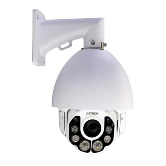
AVM5937
5MP
PTZ
30X Optical
EaZy
Zoom
Networking
FEATURES
Zoom lens of f4.5 ~ 135mm with
optical zoom and auto
suitable for various monitoring
environments
PTZ control
- Capable of
360° pan rotation continuously
with the
tilt movement of -6° ~
quick and smooth action of the camera lens
-
Hot Point
support to quickly move the
camera to the specified point remotely
- Up to
256 preset points
groups
programmable for multiple points
monitoring, and
External alarm I/O device
connection
ONVIF
(
to simplify system integration
POE (Power-over-Ethernet)
to eliminate the use of power cables and
reduce installation costs
PoE
WDR
MicroSD
External
Card
I/O
Recording
5MP 30X Speed Dome Camera
30x
focus,
for seamless monitoring:
90°, allowing
&
four sequence
auto pan
) standard supported
support
Audio
Mobile
Surveillance
MicroSD card support (up to 64GB) for
video storage
WDR
overexposure and dark areas
Line in / out
transmission
IR effective range up to
more when the
IP66
Remote Surveillance
Fully compatible
--
Android
Explorer
-- Free PC program,
devices monitoring on Windows operating
system
Push Video
--
Android devices when used with Push Video
NVR series.
to increase image recognizability in
jacks available for audio
200 meters
IR Turbo
mode is on
for outdoor application
iOS
with
Internet
devices, and
on Windows operating system
CMS Lite
, for 32CH
available on your iOS and
or
and
Advertisement
Table of Contents

Related Manuals for Avtech AVM5937


Summary of Contents for Avtech AVM5937
- Page 1 AVM5937 Audio 30X Optical EaZy MicroSD External Mobile Zoom Networking Card Surveillance Recording 5MP 30X Speed Dome Camera FEATURES Zoom lens of f4.5 ~ 135mm with MicroSD card support (up to 64GB) for optical zoom and auto...
-
Page 2: Specifications
SPECIFICATIONS ▓ Network LAN Port LAN Speed 10/100 Based-T Ethernet Data Transmission Speed 10/100/1000 Based-T DDNS, PPPoE, DHCP, NTP, SNTP, TCP/IP, ICMP, SMTP, FTP, HTTP, RTP, RTSP, Supported Protocols RTCP,IPv4/IPv6, Bonjour, UPnP, DNS,UDP,IGMP, QoS, SNMP ONVIF Compatible YES (Profile S) Number of Online Users (1) Multiple user access levels with password Security... - Page 3 SPECIFICATIONS (CONTINUED) ▓ Audio Line in YES (Mono) Line out YES (Mono) ▓ PTZ Mechanism Pan Range 360° continuous rotation Max. Pan Speed 90º/s Tilt Range -6° ~ 90° Max. Tilt Speed 70º/s Zoom Ratio 30X Optical Zoom / 16X Digital Zoom Max.
- Page 4 805z CAMERA INSTALLATION To check the complete user manual, scan the QR code or go to www.surveillance-download.com/user/m571.swf To download the free PC CMS software (CMS Lite), please check the supplied CD or go to www.surveillance-download.com/user/m571.swf Installation 1 Step 1: Set the camera ID and baud rate when this camera is going to be used with other brand’s NVR. ...
- Page 5 CABLE OVERVIEW INSERT A MICRO SD CARD The data originally saved in the microSD card (if any) will be removed after inserting it to the camera. Cable Description The camera doesn’t support hot-swapping. Please insert or remove the microSD card with power Power cable Connect to the supplied adapter.
- Page 6 SET CAMERA ID AND BAUD RATE Before connecting this camera to other brand’s NVR, you may need to manually set the ID & baud rate for the camera to work properly. Please check the description below for details. Note: The on / off of the DIP switch is shown as gray.
- Page 7 701z CAMERA INSTALLATION TYPE1 Step 1: Loosen the screws on the dome cover to remove it (as shown in Figure 1), and take all EPE foam rolls off in the camera. NOTE: When you remove the EPE foam rolls, please be careful not to damage the inner mechanism of the camera. Step 2: Install a microSD card if needed.
- Page 8 TYPE2 Step 1: (Optional) Insert the microSD card if needed Step 2: Arrange the position of the cables on the wall, pass the cables through the bracket, and secure the bracket to the wall with four screws Figure 1 Note: The four screws used to secure the bracket to the wall are not supplied in the sales package.
- Page 9 701z WATERPROOF KIT (For selected models only) CABLE OVERVIEW DEFAULT VALUES Cable Description IP address 192.168.1.10 Power cable DC12V power supply. Port number RJ45 network Connect it to a RJ45 cable. User name admin cable* Password admin A wire or a wire connected to a terminal block depending on the model you It's strongly recommended to change the default...
- Page 10 703z CAMERA INSTALLATION To check the complete user manual, scan the QR code or go to www.surveillance-download.com/user/m571.swf To download the free PC CMS software (CMS Lite), please check the supplied CD or go to www.surveillance-download.com/user/m571.swf Installation 1 TYPE1 ...
- Page 11 Note: Here shows how to install the camera with the optional bracket mentioned on the left. TYPE2 Step 1: Find the bracket and remove its upper cover, and install the bracket to the wall. Before attach the bracket to the wall, make sure how the cabling should go: ...
- Page 12 703z CABLE OVERVIEW For Type 1 For Type 2 Cable Description Cable Description Power cable Connect to the supplied adapter. Power cable DC12V power supply. RJ45 network cable* Connect to an Ethernet network cable. RJ45 network cable* Connect it to a RJ45 cable. Terminal block A wire or a wire connected to a terminal block depending on the model you have, reserved for external alarm device connection.
- Page 13 SYSTEM CONNECTION 1. Connect IP cameras and a monitor to the NVR, and power on the NVR, as illustrated below. 2. Wait till each camera is configured automatically and you will see camera images on the monitor soon. Note: Local connection only allows monitoring locally.
-
Page 14: Installation
739z Package Content Cable Overview Before starting to set up your camera, please make sure items below Cable Description in your box: Power cable DC12V, 1.5A power supply. RJ45 network cable Connect it to a RJ45 cable. Ground wire QUICK GUIDE Reserved for external alarm device Alarm-in... -
Page 15: Insert Microsd Card
Insert MicroSD Card Default Values Step1: Remove the four screws upside the camera lens and gently open the shell as indicated in Figure 1. IP address 192.168.1.10 Step2: Remove the two screws before taking out the inner part of the lens. Then, insert the MicroSD card as indicated in Figure 2. Port number Note: The data originally saved in the microSD card (if any) will be removed after inserting it to the camera. - Page 16 SPEED DOME IP CAMERA SERIES OPERATION GUIDE Please read instructions thoroughly before operation and retain it for future reference. m571_571A_571B(F)_583(H/F)_592_591a_operation_V1.2...
-
Page 17: Important Safeguard
IMPORTANT SAFEGUARD All lead-free products offered by the company comply with the requirements of the European law on the Restriction of Hazardous Substances (RoHS) directive, which means our manufacture processes and products are strictly “lead-free” and without the hazardous substances cited in the directive. The crossed-out wheeled bin mark symbolizes that within the European Union the product must be collected separately at the product end-of-life. - Page 18 MPEG4 Licensing THIS PRODUCT IS LICENSED UNDER THE MPEG4 VISUAL PATENT PORTFOLIO LICENSE FOR THE PERSONAL AND NON-COMMERCIAL USE OF A CONSUMER FOR (i) ENCODING VIDEO IN COMPLIANCE WITH THE MPEG4 VISUAL STANDARD (“MPEG-4 VIDEO”) AND/OR (ii) DECODING MPEG4 VIDEO THAT WAS ENCODED BY A CONSUMER ENGAGED IN A PERSONAL AND NON-COMMERCIAL ACTIVITY AND/OR WAS OBTAINED FROM A VIDEO PROVIDER LICENSED BY MPEG LA TO PROVIDE MPEG4 VIDEO.
-
Page 19: Table Of Contents
TABLE OF CONTENTS 1. OVERVIEW ............................1 1.1 Product Features ............................1 1.2 Package Content ............................1 1.2 Cable Overview ............................1 1.4 External Alarm Connection ........................2 1.5 Insert a Micro SD card (For selected models only) ................... 2 ... - Page 20 3.8.3 Server Log ..............................27 3.8.4 Online ................................28 3.8.5 Account ................................28 3.8.6 Google Maps ..............................29 3.8.7 Maintenance ..............................29 APPENDIX 1 BIT RATE TABLE FOR REFERENCE ................31 APPENDIX 2 Q&A ..........................33 APPENDIX 3 RECORDING TIME TABLE ....................
-
Page 21: Overview
1. OVERVIEW 1.1 Product Features EaZy Networking with your iOS® / Android™ mobile device External alarm I/O device connection -- For more accurate detection -- Possible to enable active event notifications to your iOS® & Android™ mobile devices (Push Video) when used with Push Video NVR series ... -
Page 22: External Alarm Connection
1.4 External Alarm Connection This camera supports external I/O device connection for easy connection. Below shows you how to connect an external device to this camera. DC 5V Relay DC 12V Power Supply Buzzer Camera Magnetic Contact 1.5 Insert a Micro SD card (For selected models only) For local video recording, a micro SD card slot can be found on the camera. -
Page 23: Camera Access With Internet Explorer
2. CAMERA ACCESS WITH INTERNET EXPLORER ® ® ® This camera can be accessed via Microsoft Internet Explorer , and iOS / Android™ mobile devices with our self-developed program “EagleEyes” installed depending on different using situations. ® Note: For details about accessing this camera via iOS / Android™... - Page 24 Function Icon User Level Description Supervisor / Power User Switch to the live view page. Live / Normal User / Guest Switch to the DPTZ configuration page. Supervisor / Power User DPTZ / Normal User For details, please refer to “2.3 Digital PTZ (DPTZ) Operations” at page 5. Enter the event record list for video playback.
-
Page 25: Pan- / Tilt-Move Manually
Function Icon User Level Description Live player Supervisor / Power User Select the image player from the drop-down list: / Normal User / Guest ActiveX QuickTime QuickTime is Apple Inc.’s multimedia software. You need to have QuickTime installed in your operating system before selecting “QuickTime”. When it is selected, you will be promoted to enter the user name and password to access the camera. -
Page 26: Event Record Search & Playback
2.4 Event Record Search & Playback This camera can only save a few recordings. Note: To save more recorded data, it’s recommended to use this camera with the compatible NVR. Click to jump to the next / previous time interval in an hour, for example, 11:00 ~ 12:00 or 14:00 Previous / Next Hour ~ 15:00, and start playing the earliest event video clip recorded during this whole hour. -
Page 27: Camera Configurations
3. CAMERA CONFIGURATIONS Users can further configure this camera by accessing via Internet Explorer. 3.1 System configuration menu Click “Config.” to enter the configuration page. Note: You need to be “Supervisor” to enter the system configuration page. If you’re not a “Supervisor”, please re-log into the camera with the correct user name and password. -
Page 28: Network
Main Menu Sub-Menu Reference Adjust the camera parameters if necessary. Camera Advanced Configure the camera to return to the specified point or specific cruise action when the camera Home is not in use for a specific time. This function should be used with the mini-guard control switch for alarm system integration. For details, please check with your distributor or installer. -
Page 29: Qos
3.2.2 QoS QoS, Quality of Service, is the ability to control the data flow for real-time streaming. This function is important if your network bandwidth is insufficient and you have other devices to share the network bandwidth. Check “QoS Enable”, and set the max. upload rate from 256 to 10240 kbps. 3.2.3 DDNS Select “On”... -
Page 30: Mail
3.2.6 MAIL Enter the detailed e-mail information and click “Save” to confirm. The information you set here will be applied when “Email” is selected in “Trigger” → “Trigger”. Function Description SMTP Server Enter the SMTP server address provided from your e-mail system supplier. Port Enter the port number provided from your e-mail system supplier. -
Page 31: Filter
Function Description System The text messaging service provider is Clickatell. User name / Password Enter the account user name and password you created in Clickatell. API ID Enter the API ID you applied from Clickatell. Recipient Click “Add” to enter the phone number, including the country code, to receive the text message. -
Page 32: Upnp / Bonjour
3.2.9 UPnP / Bonjour “UPnP” stands for “Universal Plug and Play”, which allows devices to connect seamlessly in the home and corporate environments and simplify installation of computer components, and is only suitable for Microsoft Windows-based operating system. “Bonjour” functions the same as “UPnP”, but it’s only suitable for Apple Mac-based operating system. ... -
Page 33: Rtp
3.2.10 RTP The Real-time Transport Protocol (RTP) is an Internet protocol standard to manage the real-time transmission of multimedia, such as VLC player. The media player you want to use for remote access must support RTP transmission for this function to work normally. - Page 34 Enable SNMP V1 / V2C Select “Yes” to enable this function, and enter the names of “Read community” and “Write community” based on your NMS configurations. To enable “Traps” to notify the management station of important events, choose “V1” or “V2C” in “Enable”, enter the address and community name, and select the event type(s) needed.
-
Page 35: Ieee 802.1X
3.2.12 IEEE 802.1X The settings here enable the camera to access a network protected by 802.1X/EAPOL (Extensible Authentication Protocol Over LAN). Note: For authentication to work properly, it's important to synchronize the time in the camera with an NTP server. Before using this function, make sure: The switch and RADIUS server you have in the LAN environment supports IEEE 802.1X, and IEEE 802.1X ... -
Page 36: Network Failure Detection
Note: Please check “APPENDIX 6 PREREQUISITES FOR NETWORK SHARE” at page 46 for more details. Enable this function, and enter the address of the PC, the folder being shared, and the user name and password to access the PC. If the information is all correct, you'll see a check in the “Status” column, and you’re ready to go to “Trigger”... -
Page 37: Preset
3.3.2 Preset Note: Before using this function, make sure the DPTZ function is enabled. You can set new preset points (up to 16) or check existing points here. How to set a new preset point Step1: Click to where you want to see, and you’ll get a 5x zoom-in image. To slightly zoom out, draw a square from the bottom right to top left, and you’ll get a 3x image. - Page 38 Auto Pan When “Auto Pan” is selected here and is clicked on the live view page, the camera will start panning. Sequence When “Sequence” is selected here and is clicked on the live view page, the camera will start patrolling each preset point defined in “Sequence”.
-
Page 39: Auto Tracking
3.3.4 Auto Tracking Set the surveillance area for auto tracking, and the tracking timeout. When the locked target is out of the pre-defined surveillance area or stops moving for a pre-defined period of time, the camera returns to the point it originally monitors. Item Description Limit 1... -
Page 40: Roi
3.3.6 ROI ROI, Region of Interest, is used to reinforce the image quality of the selected area(s). Users could specify two areas in the camera view. 3.3.7 Color Adjust the color performance from Brightness, Contract, Hue and Saturation. Click and drag the slider to preview the color change on the right side of ths page and adjust the image color. -
Page 41: Advanced
3.3.9 Advanced Adjust the camera parameters if necessary. Item Description Fixed Shutter Shutter Speed is a function that can adjust the duration of the electronic shutter to produce optimum image quality. Select the shutter speed suitable for your environment. Shutter Speed Select the shutter speed suitable for your environment. -
Page 42: Home
3.3.10 Home Configure the camera to return to the specified point or specific cruise action when the camera is not in use for a specific time. 3.4 VA 3.4.1 TA TA, tampering alarm, should be used with the mini-guard control switch for alarm system integration. For more details, please check with your distributor or installer. -
Page 43: Record Timer
3.5.2 Record Timer To schedule alarm and motion recording, enable it, and select the day and time for recording. Note: The timer must be enabled for the record function to work properly. Note: The timer for external alarms is for selected models only. Note: The selected time will be yellow-colored. - Page 44 Detect Item Description External Alarm Enable or disable detection from external alarm-in device, and click the title “External Alarm” (in blue) to set “N.O.” or “N.C.” depending on the configuration of your alarm-in device. Motion Enable or disable motion detection. Motion detection is not supported when the stream format is Motion JPEG.
-
Page 45: Push Video
3.7.2 Push Video “Push Video” is an active notification system integrated with smart phones. Users are able to receive alarm notifications within 5 seconds after event occurrence, check what happened with video playback, and take actions immediately. Note: For Push Video to work properly, make sure the record function is on in “Record” “Record”, and the record timer for the external alarm is on in “Record”... -
Page 46: Snapshot
3.7.3 Snapshot Enable this function to schedule the camera to take snapshots periodically or at a specific time, and send the snapshots to E-Mail, FTP, and / or Network Share for backup. Note: Before using E-Mail, FTP and Network Share, make sure the related configurations are done in “Network”... -
Page 47: Time
3.8.2 Time Set daylight saving time and the current time, and click “Save” to confirm. Function Description Time Configuration Set the current date. Date Set the current time. Time Daylight Saving Time Configuration Specify whether to use daylight saving time (Enable / Disable). Daylight Saving Time If this function is enabled, set the time period (Start Time / End Time), and adjust the daylight saving time in hours (Adjust Time). -
Page 48: Online
3.8.4 Online You can check the current online user(s) with respective online information. To refresh the list, click “Reload”. To allow anonymous login, select “Enable” in “Anonymous Viewer Login”. To disable image code verification at login, select “No” in “Login with CAPTCHA Image”. 3.8.5 Account You can create a new account with different user access privilege, or delete or modify an existing account setting. -
Page 49: Google Maps
3.8.6 Google Maps This function is used to let you know where the camera is. The system will prompt you to apply a Goole Maps Key if your access is denied. Please follow the instructions below when you’re denied: Step1: Click “Sign up for a Google Maps key” to enter the application page. Step2: Check the terms and conditions, and enter the IP address of the camera. -
Page 50: System Reboot
Step2: Select “Upgrade” to start system upgrading. Note: You’ll be prompted to keep current configurations. It’s recommended to keep them, or all configurations will be restored to default values after upgrade. Note: It takes a few minutes to finish the upgrade process. Do not disconnect the power during firmware upgrade, or the upgrade may be failed. -
Page 51: Appendix 1 Bit Rate Table For Reference
APPENDIX 1 BIT RATE TABLE FOR REFERENCE The data below is for reference only. The bit rates listed here may vary depending on the resolution, image quality & frame rate you choose, the complexity of your monitoring area, and how often the moving objects show in your monitoring area. Testing Environment ... - Page 52 Resolution Quality Frame Rate (Dynamic) kbps (Static) kbps SXGA Best 1/15 High Normal Basic Best High Normal Basic QVGA Best High Normal Basic...
-
Page 53: Appendix 2 Q&A
APPENDIX 2 Q&A I can connect to this camera in my house or office where it’s installed with wireless network. But when I leave my house or office, I can’t connect to it from my mobile phone (with 3G network), or other PC (connected to Internet). - Page 54 Step2: Click “Sign-in & Security.” Step3: Roll down to the bottom of the page and check the “Allow less secure apps.”...
-
Page 55: Appendix 3 Recording Time Table
APPENDIX 3 RECORDING TIME TABLE Below shows the estimated total recording time for each recording resolution. The recording time per resolution is the average value collected from the both alarm trigger conditions indicated in “Testing Environment”, and is for reference only. The time may vary depending on the resolution, image quality &... -
Page 56: Appendix 4 Api Id Application For Sms Messaging
APPENDIX 4 API ID APPLICATION FOR SMS MESSAGING To allow the camera automatically sending a text message when an event happens, you need to apply an API ID from a mobile messaging company first, such as Clickatell or EVERY8D. Below shows an example of how to get an API ID from Clickatell. Note: The SMS messaging may not be totally free. - Page 57 Step4: In your account, find “Connection Status” and create a connection (API ID). Step5: Select “HTTP/S”. Give a meaning name for this connection, and click “Submit and Get API ID”. Step5: An API ID will be generated as follows. Note: Note down the API ID for SMS notification setting later.
-
Page 58: Appendix 5 Product Specifications
APPENDIX 5 PRODUCT SPECIFICATIONS Model 1 Model 2 Model 3 ▓ Network LAN Port LAN Speed 10/100 Based-T Ethernet DDNS, PPPoE, DHCP, NTP, SNTP, TCP/IP, ICMP, SMTP, FTP, HTTP, RTP, RTSP, RTCP,IPv4, Bonjour, UPnP, Supported Protocols DNS,UDP,IGMP, QoS, SNMP Number of Online Users ONVIF Compatible (1) Multiple user access levels with password Security... - Page 59 Model 1 Model 2 Model 3 ▓ PTZ Mechanism Pan Range 360° Max. Pan Speed 120º/s Tilt Range 90° Max. Tilt Speed 90º/s Zoom Ratio 10X Optical Zoom Max. Zoom Speed Approx. 3s (Tele ~ Wide) Preset Points Up to 16 preset points 1.
- Page 60 Model 4 ▓ Network LAN Port LAN Speed 10/100 Based-T Ethernet DDNS, PPPoE, DHCP, NTP, SNTP, TCP/IP, ICMP, SMTP, FTP, HTTP, RTP, RTSP, RTCP,IPv4, Bonjour, UPnP, Supported Protocols DNS,UDP,IGMP, QoS, SNMP Number of Online Users ONVIF Compatible (1) Multiple user access levels with password Security (2) IP address filtering (3) Digest authentication...
- Page 61 Model 4 ▓ PTZ Mechanism Pan Range 360° endless Max. Pan Speed 180º/s Tilt Range 180° Max. Tilt Speed 100º/s Zoom Ratio 20X Optical Zoom Max. Zoom Speed Approx. 3s (Tele ~ Wide) Preset Points Up to 16 preset points 1.
- Page 62 Model 5 ▓ Network LAN Port LAN Speed 10/100 Based-T Ethernet DDNS, PPPoE, DHCP, NTP, SNTP, TCP/IP, ICMP, SMTP, FTP, HTTP, RTP, RTSP, RTCP,IPv4, Bonjour, UPnP, Supported Protocols DNS,UDP,IGMP, QoS, SNMP Number of Online Users ONVIF Compatible (1) Multiple user access levels with password Security (2) IP address filtering (3) Digest authentication...
- Page 63 Model 5 ▓ PTZ Mechanism Pan Range 360° endless Max. Pan Speed 180º/s Tilt Range -3° ~ 90° Max. Tilt Speed 100º/s Zoom Ratio 20X Optical Zoom Max. Zoom Speed Approx. 3s (Tele ~ Wide) Preset Points Up to 256 preset points 1.
- Page 64 Model 6 ▓ Network LAN Port LAN Speed 10/100 Based-T Ethernet DDNS, PPPoE, DHCP, NTP, SNTP, TCP/IP, ICMP, SMTP, FTP, HTTP, RTP, RTSP, RTCP,IPv4, Bonjour, UPnP, Supported Protocols DNS,UDP,IGMP, QoS, SNMP Number of Online Users ONVIF Compatible (1) Multiple user access levels with password Security (2) IP address filtering (3) Digest authentication...
- Page 65 Model 6 ▓ PTZ Mechanism Pan Range 360° endless Max. Pan Speed 180º/s Tilt Range 90° Max. Tilt Speed 90º/s Zoom Ratio 10X Optical Zoom Max. Zoom Speed Approx. 4s (Tele ~ Wide) Preset Points Up to 256 preset points 1.
-
Page 66: Appendix 6 Prerequisites For Network Share
APPENDIX 6 PREREQUISITES FOR NETWORK SHARE A6.1 Check PC IP Address Note: The instructions below are taking Windows 7 and 8 for an example. Step1: Go to "Network and Sharing Center”, and select “Change adapter settings”. Step2: Right-click on “Local Area Connection”, and select “Properties”. Note: If your local area connection is not enabled, please also enable it. -
Page 67: A6.3 Share Folder
Step2: Set a user name, and choose “Administrator” for this account. Then, click “Create Account”. Step3: Set the password, and click “Create Account”. A6.3 Share Folder Note: The instructions below are taking Windows 7 and 8 for an example. Step1: Right-click the folder you want to use to save snapshots for “Network Share”, and choose “Properties”. Step2: In “Share Properties”, select the tab of “Sharing”, and choose “Share…”. - Page 68 Step3: Choose the account you want to share with, and click “Share” to save.
-
Page 69: Appendix 7 Enable Push Video
APPENDIX 7 ENABLE PUSH VIDEO A7.1 What’s Push Video “Push Video” is an active notification system, different from traditional FTP & Email notification methods. It’s more active and stable, but also easier to be affected by your network bandwidth. When “Push Video” is enabled and any alarm event occurs, you’ll be able to receive notifications on your iPhone / iPad / Android mobile device within 5 seconds. -
Page 70: A7.3.2 From Android Mobile Device
A7.3.2 From Android Mobile Device In the address book, switch “Guard” from “OFF” to “ON”. -
Page 71: Appendix 8 Eazy Networking
Note: This function is for selected models only. EaZy Networking is a free P2P cloud service to connect AVTECH devices to the Internet automatically by plug-and-play, enabling you to check the live view via your mobile device or laptop at anytime. - Page 72 Step3: Open Internet Explorer, and enter the IP address and port number you found to enter the login page. The format is: http://ipaddress:port. Enter the user name and password to login. The default user name and password are both ”admin”. Then, choose ”Config.”...
- Page 73 Step7: (Optional) If your camera has LED indicators, make sure both indicators are always on, and select “Yes” to continue. Step8: Enter or scan the MAC address. - Find the address sticker on the camera starting with “000E53”, and type it manually. Or, - Access the camera as shown in Step3 to scan the QR code.
-
Page 74: A8.1.2 Checking Remaining Data Allowance
A8.1.2 Checking Remaining Data Allowance Step1: Log into the cloud service. Step2: Select “Details” to go to account information, and select “Available Data Allowance”. A8.1.3 Sharing Cloud Device Access with Other Account(s) Note: One cloud device could be shared up to 30 cloud accounts, but the access to the device might be failed because it is still restricted to the maximum online user setup of the device. - Page 75 Step4: Check again the account with which you want to share your cloud device, and select “Next” to confirm and continue. Step5: Specify the access permission of the specified account, which account’s data allowance should be consumed after access successfully, and how long the account is allowed to stay after access successfully. ...
-
Page 76: A8.2 Via Internet Explorer On Pc / Laptop
A8.2 Via Internet Explorer on PC / Laptop Note: EaZy Networking setup via a web browser is only available on Internet Explorer. A8.2.1 Setup Step1: Find a laptop and connect it to the same router physically (with a RJ45 network cable) or wirelessly as the one to which the camera is connected. - Page 77 Step4: Open Internet Explorer on a PC / laptop, and enter https://ez.eagleeyes.tw. In the login page, register an account for “Cloud Service”. If you’ve got an account, please just log in. Note: You PC must be connected to Internet. Step4: Click + on the left pane, and you’ll be prompted to install plugins: EaZy Control and EaZy Wizard. Please follow the instructions to install these two plugins to ensure the service works properly.
- Page 78 Step7: When your device is found, you’ll be directed to the next page to change the device title if you want. Note: The device name changed here will be fixed and can’t be changed later. Click “Apply” to continue. You’ll be prompted to confirm if you want to remove the default user name and password.
-
Page 79: A8.2.2 Checking Remaining Data Allowance
A8.2.2 Checking Remaining Data Allowance Step1: Log into the cloud service. Step2: Select “Account Information” on the top right corner to go to account information, and select “Available Data Allowance”. A8.2.3 Sharing Cloud Device Access to Other Account(s) Note: One cloud device could be shared up to 30 cloud accounts, but the access to the device might be failed because it is still restricted to the maximum online user setup of the device. - Page 80 Step5: Specify the access permission of the specified account, which account’s data allowance should be consumed after access successfully, and how long the account is allowed to stay after access successfully. Who should pay data allowance: Who should pay The order to consume data allowance data allowance The free data allowance provided by the device ->...
-
Page 81: A8.3 Icons
The cloud icon will be grayed out if the EaZy server can’t be connected. You’ve shared the access right of the device with other cloud account via Buddy (AVTECH Cloud Service). Depending on the device color The icon will be grayed out if you disable the device share. - Page 83 11cm Drill Hole Drill Hole Ø1.2cm Ø1.2cm 15cm Drill Hole Drill Hole Ø0.9cm Ø0.9cm Reserved for the cable for go along the wall.
-
Page 84: Advanced Network Setup
ADVANCED NETWORK SETUP For wired network camera Please read instructions thoroughly before operation and retain it for future reference. network_ipcam_V0.9... - Page 85 IMPORTANT SAFEGUARD All lead-free products offered by the company comply with the requirements of the European law on the Restriction of Hazardous Substances (RoHS) directive, which means our manufacture processes and products are strictly “lead-free” and without the hazardous substances cited in the directive. The crossed-out wheeled bin mark symbolizes that within the European Union the product must be collected separately at the product end-of-life.
- Page 86 MPEG4 Licensing THIS PRODUCT IS LICENSED UNDER THE MPEG4 VISUAL PATENT PORTFOLIO LICENSE FOR THE PERSONAL AND NON-COMMERCIAL USE OF A CONSUMER FOR (i) ENCODING VIDEO IN COMPLIANCE WITH THE MPEG4 VISUAL STANDARD (“MPEG-4 VIDEO”) AND/OR (ii) DECODING MPEG4 VIDEO THAT WAS ENCODED BY A CONSUMER ENGAGED IN A PERSONAL AND NON-COMMERCIAL ACTIVITY AND/OR WAS OBTAINED FROM A VIDEO PROVIDER LICENSED BY MPEG LA TO PROVIDE MPEG4 VIDEO.
- Page 87 TABLE OF CONTENTS 1. Check Your Network Environment ...................... 5 2 Wireless Router + Modem ........................6 2.1 Configure on Laptop / Computer ....................... 6 2.2 Configure with iOS devices (iPhone / iPad) ....................8 2.3 Configure with Android mobile devices ....................10 3 Router + Modem ..........................
-
Page 88: Check Your Network Environment
1. Check Your Network Environment Please follow the instructions below to finish camera installation and network configurations. Check your network environment and see which category you have: If you’re using: Wireless router + modem, please refer to “2 Wireless Router + Modem”. ... -
Page 89: Wireless Router + Modem
2 Wireless Router + Modem You may use your laptop / computer, or your iOS (iPhone / iPad) and Android mobile device to complete the network configuration of the camera. Note: Network setup with your iOS (iPhone / iPad) and Android mobile device is available only for EaZy Networking, Push Video, and ETS camera series. - Page 90 Step4: Open Internet Explorer on your laptop / computer, and enter the IP address and port number you just found in the URL column to access this camera. The format is http://ipaddress:portnum, such as http://192.168.2.25:88 in our example. In the login page, enter the user name, password, and security code to access. Note: Please skip the wizard.
-
Page 91: Configure With Ios Devices (Iphone / Ipad)
2.2 Configure with iOS devices (iPhone / iPad) Before configuring this camera on iPhone / iPad, make sure: You’ve installed our mobile app, EagleEyes, in your iPhone / iPad. Note: If you haven’t installed EagleEyes, please go to “App Store” and search “eagleeyes”. The free version of EagleEyes is EagleEyes (Lite) for Android 1.6 (or later) or EagleEyes(Lite+) for Android 2.2 (or later). - Page 92 Step2: Open “EagleEyes” on your iPhone or iPad. In the address book, click “+” to add new device. Then, select “Local Network Search” to search your network camera. You’ll see an IP address assigned by your router. If you connect two or more cameras to the wireless router, you’ll see many cameras with different IP addresses after searching.
-
Page 93: Configure With Android Mobile Devices
Step5: In the new device page, give a meaningful name for this connection in “Title”, and click “Save”. Please continue with configuring port forwarding as instructed in “APPENDIX 3 CONFIGURE PORT FORWARDING” at page 23. Check your connection Step1: Switch the network mode to 3G mode on iPhone or iPad. Step2: Start EagleEyes, and select the connection you just added to see if you can access the camera successfully. - Page 94 Step3: Select the IP address you want to configure to show the IP address setting page. Then, click the drop-down list of “Network” to change the network type from “DHCP” to “Static”. The default port number is 88. You may change it to any value (such as 8080) if you know the port number of 88 is blocked.
- Page 95 Step5: In the new device page, give a meaningful name for this connection in “Title”, and click “Save”. Step6: Go to “Check your connection” below to examine your connection. Check your connection Step1: Switch the network mode to 3G mode on your android device. Step2: Start EagleEyes, and select the connection you just added to see if you can access the camera successfully.
-
Page 96: Router + Modem
3 Router + Modem You may use your laptop / PC to complete the network configuration of the camera. Before configuring this camera on your laptop / PC, make sure: Your Windows operating system is Windows 7, Vista or XP. ... - Page 97 If your router supports UPnP, please proceed Step7. If your router doesn’t support UPnP, click “Save”, and access your router for port forwarding as instructed in “APPENDIX 3 CONFIGURE PORT FORWARDING” at page 23. Step5: Go to “UPnP”, and enable the UPnP service. Then, enable “Port Mapping”, and click “Save”...
-
Page 98: Modem / Hub + Modem
4 Modem / Hub + Modem You may use your laptop / PC to complete the network configuration of the camera. Before configuring this camera on your laptop / PC, make sure: Your Windows operating system is Windows 7, Vista or XP. ... - Page 99 Item Description Account Change your default account password if needed. This change can also be made in “Config.” “General” “Account”. Date and Time Check and select the current date and time. Network Configure your network setting based on the network type you’re using. For details, please refer to Step4 &...
- Page 100 a) Enable DDNS. b) Select “default” in “System Name”. c) In “Hostname”, keep the default value, i.e. the MAC address of this camera. Then, note down the whole address of the camera, for example, MAC000e531d6ff1.ddns.eagleeyes.tw. d) (Optional) Enter your email address to receive messages from the DDNS server. Note: Please at least use the default address to access your network camera remotely once.
-
Page 101: Change Default Account
5 Change Default Account To ensure your account safety, please access the camera after network configuration to change the default user name and password with new one you prefer. 5.1 From Web Browser Log into the camera, and select “Config.” “General” “Account”. Select the default account “admin”, and click “Edit”... -
Page 102: Appendix 1 Change Ip Address Of Your Laptop / Pc
APPENDIX 1 CHANGE IP ADDRESS OF YOUR LAPTOP / PC For LAN connection with this network camera, you need to change the IP address of your laptop / PC to 192.168.1.xxx (1~255, except 10) first. Note: Before changing the IP address, make sure you note down the original IP address setting of your laptop / PC. - Page 103 For Windows Vista users: ” (start) “Control Panel” “Network and Internet” to enter the “Network and Sharing Center”. a) Select “ Then, click “Manage network connections” (If you’re in “Category View”). b) Right-click on “Local Area Connection”, and select “Properties”. Note: If your local area connection is not enabled, please also enable it.
- Page 104 b) Right-click on “Local Area Connection”, and select “Properties”. Note: If your local area connection is not enabled, please also enable it. c) In the “Networking” tab, select “Internet Protocol Version 4 (TCP/IPv4)”, and select “Properties”. d) In the “General” tab, select “Use the following IP address”, and set the IP address as described below. Note: It’s recommended to note down the current settings first and then change as instructed.
-
Page 105: Appendix 2 Mobile Surveillance Via Eagleeyes
APPENDIX 2 MOBILE SURVEILLANCE VIA EAGLEEYES EagleEyes is a mobile phone program used with our surveillance system for remote surveillance. It has several advantages: It’s free (Except EagleEyes Plus for iPhone, EagleEyesHD Plus for iPad, and EagleEyes(Plus+) for Android mobile devices). -
Page 106: Appendix 3 Configure Port Forwarding
APPENDIX 3 CONFIGURE PORT FORWARDING You need to additionally access your router for port forwarding when your router doesn’t support UPnP. Each router has different setting page. Here we’re taking D-Link wireless router as an example. Step1: Access your router for port forwarding. ...
Need help?
Do you have a question about the AVM5937 and is the answer not in the manual?
Questions and answers