Table of Contents
Advertisement
Quick Links
QUICK GUIDE
Please read instructions thoroughly before operation and retain it for future
reference. Online manual download:
www.surveillance-download.com/user/m521.swf
Installation
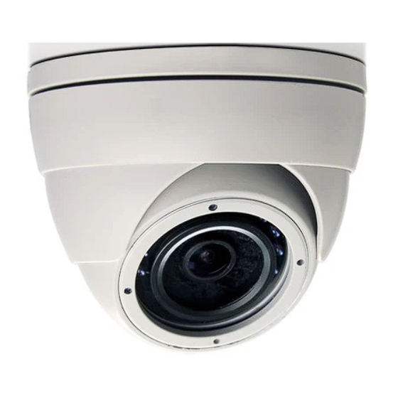
Type 1
Step 1: Uncover the dome camera by loosening the screws on the housing with the supplied wrench.
Step 2: Locate the three holes as illustrated in the right picture. They are where the three supplied screws belong.
Step 3: Mark the locations of the three screw holes on the ceiling or the wall, and drill a hole for each on the
ceiling or the wall.
Step 4: Screw the camera in place.
Step 5: Power up your camera.
Step 6: Check the viewing angle on the PC.
Step 7: Adjust the position and the viewing angle of the camera, if necessary.
Step 8: Replace the dome cover and have the three screws on it tightened.
Note: For clear images, please clear of fingerprints the inner part of the dome cover against the lens.
Package Content
Before starting to set up your camera, please make sure items below in your box:
Standard package:
Type 1
or Type 2
Camera
Quick Guide
Optional accessories
:
(For Type 1 only)
Screws & Wall Plugs x 3
Step1: Remove the camera base as shown in Figure 1, and disassemble the camera to four parts as shown in Figure 2.
Rotate anti-clockwise
Step2: Locate where you want to install this camera (wall or ceiling), and drill holes on the wall or ceiling for securing
the bracket and routing the cables (if necessary).
Step3: Attach the bracket to the wall (or ceiling), and make sure the cables are routed and arranged properly in the
bracket, as shown in Figure 3.
Step4: Secure the bracket to the wall (or ceiling), as shown in Figure 4.
Where to look
Cable Overview
Below is an overview of various cables that can be used with the camera. Besides,
it is followed by a table, which offers simple descriptions of cable connection.
Cable
CD
Power cable
RJ45 network cable*
GND
Alarm-in**
Alarm-out**
RESET
Line-in*
Line-out*
Wrench
* For PoE (IEEE802.3af) installation, make sure your network cable has the maximum cable
resistance of 20Ω, such as CAT.5e or CAT.6 cables, to conform to the standard of IEEE802.3af.
** For Type 1 only
Type 2
Remove
Figure 1
Cable routing
Figure 3
621Z
Line-in (blue)**
Line-out (green)**
RJ45 network cable
Alarm-in**
GND
RESET
GND**
Alarm-out**
Power cable
Description
DC12V power supply.
Connect it to a RJ45 cable.
Ground wire
Reserved for external alarm device connection
Reserved for external alarm device connection
Remove the insulating coating of wire, and twist it with a ground
wire together to reset default camera
Colored as blue, used to connect to a microphone for audio input.
Colored as green, used to connect to a speaker for audio output.
Camera lens
Base
Part 1
Part 2
Figure 2
Attach to wall (or ceiling)
Figure 4
m532_n332_320_320L_420_quick_V1.0
Advertisement
Table of Contents

Related Manuals for Avtech avm420s


Summary of Contents for Avtech avm420s
-
Page 1: Package Content
621Z Package Content Cable Overview Before starting to set up your camera, please make sure items below in your box: Below is an overview of various cables that can be used with the camera. Besides, it is followed by a table, which offers simple descriptions of cable connection. Line-in (blue)** ... -
Page 2: Focus Adjustment
Installation Focus Adjustment Insert MicroSD Card (Continued) (For Type 1 only) (For Type 1 only) Type 2 If you need to adjust the focus, the picture below shows you how: The data originally saved in the micro SD card (if any) will be removed Step5: Slightly adjust the camera lens to where it’s supposed to after inserting it to the camera. -
Page 3: Camera Overview
583Z PACKAGE CONTENTS Camera Overview Type 1 Type 2 Before starting to set up your camera, please make sure items below are in your box: Standard package: QUICK GUIDE Side View (depending on the model you use ) Camera Quick Guide ... - Page 4 INSTALLATION (Continued) Insert MicroSD Card (For selected models) Type 2 (Continued) The data originally saved in the microSD card (if any) will be removed after inserting it to the camera. Step 6: Pan, tilt and rotate the lens to adjust the The camera doesn’t support hot-swapping.
-
Page 5: Installation
651Z Package Contents Installation Step 1: Uncover the dome camera by loosening the three screws on the housing with the Before starting to set up your camera, please make sure items below are in your box: supplied wrench. Note: The three screws aren’t designed to be removed from the housing. -
Page 6: Focusing The Camera
Waterproof Accessories Installation Preview the Viewing Angle with a BNC Monitor (Selected Model Only) (Selected Model Only) This camera support composite output for you to Step 4: Install a connector to the network cable. Step 1: Pass the network cable without connector through the preview the viewing angle if it’s correct or not plastic tube cover as the right illustration.
Need help?
Do you have a question about the avm420s and is the answer not in the manual?
Questions and answers