
Subscribe to Our Youtube Channel
Related Manuals for Omtech K40+


Summary of Contents for Omtech K40+
- Page 1 K40+ Laser Engraver Control Card User Manual Read Carefully Before Use Keep for Future Reference...
- Page 2 PREFACE Thank you for choosing this laser control board. Read this manual carefully before operation. It covers the details of correct installation, adjustment, and safe operation of your laser’s new control board. It is intended to be used in conjunction with the manuals for your laser engraver and its engraving software.
-
Page 3: Table Of Contents
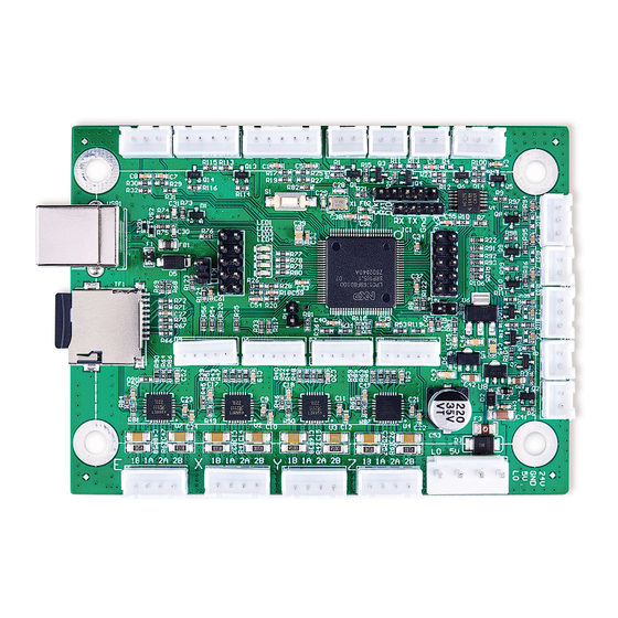
CONTENTS 1 Introduction ..............................1 1.1 Introduction Overview ........................1 1.2 Symbol Guide............................1 1.3 Designated Use............................ 1 1.4 Technical Specifications ........................2 1.5 Product Diagram ..........................2 2 Safety Information............................4 2.1 Disclaimer............................4 2.2 General Safety Instructions ......................... 4 2.3 Electrical Safety Instructions.......................4 3 Installation.............................. -
Page 4: Introduction
1.3 Designated Use This control board is intended for use with OMTech’s low-wattage laser engravers and cutters using glass (DC) or metal (RF) carbon dioxide (CO₂) tubes. Its firmware and ports can also be used to control similar engravers from other manufacturers and some CNC machines, although such configurations are outside the scope of this manual and must be done at the user’s own risk. -
Page 5: Technical Specifications
1.4 Technical Specifications Model K40+ CPU Type 32-Bit Arm Cortex-M3 Board Dimensions 3.8×2.8×0.5 in. (9.8×7.3×1.2 cm) Input Power 24V DC Output Power 5V DC Max. Clock Frequency 120 MHz Firmware Smoothie Compatible Software LightBurn (Windows/Linux/MacOS) System Memory 512 MB Compatible File Systems FAT16, FAT32 Maximum USB Speed USB 2.0 (480 Mbit/sec.) - Page 6 Multiphase X Axis Driver Signal Multiphase Y Axis Driver Signal Multiphase Z Axis Driver Signal OMTech or Bipolar U Axis Driver Signal OMTech or Bipolar X Axis Driver Signal OMTech or Bipolar Y Axis Driver Signal OMTech or Bipolar Z Axis Driver Signal...
-
Page 7: Safety Information
2. Safety Information 2.1 Disclaimer Your control board may differ somewhat from those shown in this manual due to options, updates, etc. Please contact us if your device came with an outdated manual or if you have any other questions. 2.2 General Safety Instructions Use this device only in accordance with this instruction manual, the manuals for your laser engraver and its engraving software, and all applicable local and national laws and regulations. -
Page 8: Installation
2.4 Fire Safety • NEVER leave your engraver alone during use. • Always keep a fire extinguisher, water hose, or other flame retardant system nearby in case of accidents. Ensure the local fire department’s phone number is clearly displayed nearby. In the case of a fire, cut electrical power before dousing the flame. -
Page 9: Replacing The Old Control Board
Here, “PWR” is used for the main power input, “Y” and “X” for the motor drivers, and “END” for the limit switches. Any clear phrasing is fine. If your old board already has other connections in addition to these, use its manual or the board’s markings and the diagram in §1.5 to label those wires as well. - Page 10 3.4.1 Control Board Power On the control board, find the largest 4 pin terminal. Connect the “PWR” terminal block previously removed from your old board to this terminal. If you are connecting the wires individually for a new or different system, connect the pin marked “24V”...
- Page 11 The 5 pin terminals marked “X” and “Y” in the center of the board might be necessary for some upgraded stepper motors. You can connect them directly to a preassembled terminal or wire them separately. Connect each pin marked “5V” to the positive pins (“PUL+”, “DIR+”, and “EN+”) for the corresponding axis. Connect each pin marked “GND”...
- Page 12 The 2 and 3 pin thermistor terminals (“TH1”–“TH5”) can provide similar 5V inputs from CNC thermistors or other sensors. Each accepts one or two input lines and a ground line (“GND”) between or to the right. 3.4.5 Limit Switch Connections On the control board, find the 5 pin terminal along the side next to the USB port.
- Page 13 3.4.6 Device Output Connections This circuit board can provide a 5V power feed and up to nine 5V output signals to control various ancillary devices such as external exhaust fans, pressurized air assists, and CNC heating elements. The power feed terminal has 2 pins for the current (“5V”) and the ground (“GND”).
-
Page 14: Data Connections
3.5 Data Connections The microSD card goes into its port on the side of the card. The pins on the card should face down and go in first. The slightly raised handle should face up and protrude slightly after insertion. Do not force the card into place. If you did not already do so, bolt your new control board to its holding plate, making sure that the USB port will face the casing’s access hole. - Page 15 Choose a name for your engraver (“Smoothieware” in the example picture) and enter the length of your laser engraver’s X and Y axes in millimeters. Enter the origin for your machine (select “Rear Left” for OMTech engravers) and select whether you want LightBurn to return the laser head to the origin at startup. Review the information that...
-
Page 16: Testing
After LightBurn finishes installing its connection to your engraver’s new control card, go to the Edit menu and select Device Setting. Under the Basic Settings tab, find the Other Options section and activate Enable Smoothie Clustering. 3.7 Testing Restore power to your engraver and test that all of its safety features remain fully functioning. Test that the control panel and control computer are able to move the engraver’s laser head and fire the laser correctly. -
Page 17: Maintenance
QR code to the right. Come join the OMTech community at our official laser group on Facebook or visit the company forums at omtechlaser.com! Check our YouTube channel for helpful hints and instructional videos. - Page 18 U S B - K 4 0 S - 0 0 Rev. 15 Feb. 2022...
Need help?
Do you have a question about the K40+ and is the answer not in the manual?
Questions and answers