Advertisement
Advertisement
Table of Contents

Related Manuals for Omtech Light B10


Summary of Contents for Omtech Light B10
- Page 1 Light B10 User Manual...
- Page 3 The provided module has an average lifespan around 15,000 hours before requiring replacement. Read this manual before use, keep it for future reference, contact OMTech customer service if any point is unclear, and provide it with the machine if it is ever given or sold to another person.
- Page 4 Welcome to the OMTech Community! and Happy #LaserDay! For helpful hints and instructional videos, join us at our official laser group on Facebook and visit our channel on YouTube. If you encounter any problem with your engraver, email us at support@omtechlaser.com or techsupport@omtechlaser.com any time or call us at (949) 539-0458...
-
Page 5: Table Of Contents
Contents Safety First ..............................1 Package List ............................... 2 Overview ..............................3 Setup ................................4 Standard Use ............................19 Safety Information ..........................27 Warning Labels ............................29 Maintenance Schedule ..........................30 Legal Terms .............................. 31 Warranty Activation ..........................32... -
Page 6: Safety First
Safety First! Class 4 Your Light is a laser system. ALWAYS wear your laser glasses during use and avoid direct exposure to the laser beam. ALWAYS be mindful of fumes, smoke, and debris created during engraving. Use a fume extractor if your material will produce any harmful byproducts. ALWAYS stay near your engraver during use and be ready to put out a fire if needed. -
Page 7: Package List
Package List USB Cord Support Legs X Motor Cable MicroSD Card and Reader Front Frame with Software Back Frame Air Assist Fan 10W Laser Module with Tube with Protective Shield Left Frame Focusing Tool Hex Wrench Set OD5 Laser Glasses Right Frame Power Cord X-Axis Gantry... -
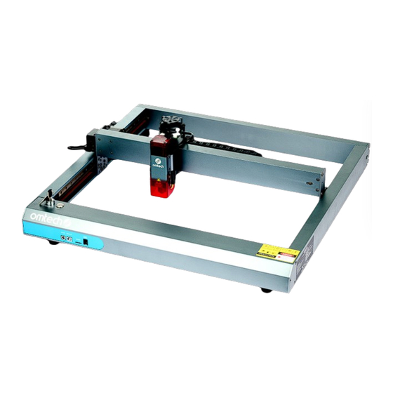
Page 8: Overview
Overview X-Axis Gantry Air Assist Fan Back Frame Right Y-Axis Left Y-Axis Tension Adjustment Locking Lever Air Assist Tube Tension Adjustment Right Y-Axis Left Y-Axis Restraining Bolt Restraining Bolt X-Axis X-Axis Stepper Motor Tension Adj. X-Axis Restraining Bolt Laser Module Rotary and Flame Detection Left Frame... -
Page 9: Setup
Setup Frame Setup Be careful of sharp edges during assembly. Wearing protective gloves is recommended. For best results, in each part of assembly, place and partially tighten all fasteners before fully tightening any. If the belts are ever too tight in any step, see the section on Belt Tensioning below for how to loosen them. - Page 10 4 Align the bolt holes in the left frame piece with those in the front piece and use three M4×10 bolts to partially connect them. 5 Do the same thing with the left frame piece and the back piece. Be sure the support legs on the back piece are facing down.
- Page 11 7 Repeat the same steps with the right frame piece. At this point, it is recommended to use a spirit level (not included) to check that all parts of the frame are completely level and plumb, adjusting their positions, legs, and fasteners as needed.
- Page 12 8 Place the X-axis gantry between its mounts on the two side pieces. The mount for the diode laser module should face towards the front of the frame. Connect the gantry to the mounts using two M4×10 bolts on each side. For best results, position and partially tighten all the bolts before fully tightening any.
- Page 13 9 Place the fan so that its three bolt holes match those on the back side of the laser mount. Fix it in place using its M3×6 bolts.
- Page 14 10 If it is not already installed, place the protective shield on the bottom of the laser head using one matching bolt on each side. Use of this shield is highly recommended but it does NOT fully block the laser in all directions. Anyone nearby the laser during use should ALWAYS wear the provided laser glasses or eye protection that is similarly powerful (OD5+) at the laser’s wavelength (400–450 nm).
- Page 15 Belt Tensioning When the belts are loosened, be careful to move them slowly and evenly. Never force movement if any belt becomes stuck. Remove any obstruction, carefully adjust them, and try again. Y-Axis Belts 1 Unlock the belt that you will adjust by turning its restraining bolt counterclockwise.
- Page 16 Internal Wiring Setup In each step, be careful that each plug is fully inserted in the correct direction and is held snugly in place. Do not force any plug into any slot in the wrong direction. 1 There should be two wires coming from the upper end of the cable manager near the laser head, one marked “1”...
- Page 17 5 There should be two other unmarked wires coming from the upper end of the same cable manager, one with a wide plug and one with a narrow plug. Connect the wide plug to the larger bottom socket on the front of the gantry and the narrow plug to the smaller top socket. 6 There should be three wires coming from the lower end of the cable manager along the left piece of the frame, one marked “2”...
- Page 18 External Wiring Setup 1 Connect the Light to your control computer using the provided USB cable. If you need to use a USB extension cable, make sure the extension cable is in good condition and all connections are firmly made. It is not recommended to have your control computer farther than 15 feet (4.5 m) away from the laser to avoid potentially dangerous interference to the control signals.
- Page 19 Software Setup 1 Your Light comes with a microSD card loaded with the open source engraving program LaserGRBL and a trial version of LightBurn. To access them, place the microSD card into its USB reader by sliding the card into the slot above the USB’s handle. The ridge on the microSD card should face up, away from the reader’s handle.
- Page 20 6 Select the Light’s COM port and Baud rate (115200) on the top left. If more than one COM port is listed, find your laser by writing down all the ports listed and then disconnecting the laser’s USB cord. The one that disappears from the list is your laser.
- Page 21 10 To use LightBurn for a free month-long trial, run its installation wizard from the LightBurn folder on the microSD card. Alternatively, you can also download the latest version of the program from its GitHub at github.com/LightBurnSoftware/deployment or from our website at omtechlaser.com/pages/software-download.
- Page 22 Initial Testing Belt Tension After all setup is completed and before you begin full use of your machine, check again that the belts are properly tensioned and that all the wires are safely placed. See Belt Tensioning above for details. Emergency Stop Because of the risk of fire and other hazards during engraving, you should test that your laser key functions as an emergency stop before conducting any further work with your...
- Page 23 Done!
-
Page 24: Standard Use
Normal Operation 1 Turn Everything On 4 Begin Engraving Turn the laser key and press the power button Put on your laser glasses. With LaserGRBL, start work by pressing ► or by going to File on the toolbar beside it. Turn on your computer, open your and selecting Send to Machine. - Page 25 The most important parameters are the focus, power, and speed settings. Together, they control the intensity of the beam as it contacts your material. FOCUS The lens has a focal length of 30 mm (about 1.18 inches) and rests 24 mm above the bottom of the laser module’s tube. For surface engraving, release the locking lever and gently lower the tube to touch the top of the provided tool each time the thickness of your material changes.
- Page 26 Pass-Through To work on longer pieces, just slide them through under the sides of the frame. If you elevate the Light to pass thicker materials through the work area, adjust the focus to match and make sure the Light is completely level and stable.
- Page 27 LaserGRBL Main Interface A. Toolbar—This area controls general configuration (Grbl), file loading and saving (File), the display theme (Colors), the display language (Language), driver installation and control board flashing (Tools), and helpful links (?). B. Connection Control—This area connects the computer to the laser. C.
- Page 28 Importing Image Files To engrave an image, go to File on the toolbar and select Open File. All compatible file types in the selected folder will be available. After you select your image, the Import Image window will open. A. Main Display—This toggles between displaying the original image and a preview of what it will look like under the window’s current settings.
- Page 29 Processing Image Files After clicking Next, you will open the Target Image window. This allows you to set the overall parameters for the current engraving session. A. Speed—This sets the maximum engraving speed in mm/min. This speed must be accelerated to after corners and edges, which can cause some areas to be engraved darker than intended.
- Page 30 Important GCode Commands Your Light can also process direct commands for movement and engraving using GCode. Commands can also be used to adjust the machine’s parameters, which can be seen by typing $$ or by going to Grbl on the toolbar and selecting Grbl Configuration. The most important commands are: Activate the laser in constant power mode Display the current parameter settings...
- Page 31 Onward and Upward! omtechlaser.com Visit to further expand your laser’s capabilities or to browse through our full range of laser products, equipment, and accessories. Protective Honeycomb Inline Fans Enclosures Beds and Ducting Metal Engraving Chuck & Roller Standardized Spray and Lasers Rotary Axes Materials...
-
Page 32: Safety Information
Safety Considerations General Safety DO NOT modify this device or disable its safety features except as Only use this device in accordance with these instructions and all applicable local and national laws and regulations. Read this manual specifically instructed by customer service or a trained technician. completely before use, keep it for future reference, and provide it ONLY use this laser when it is well placed on a stable and level with the machine if it is ever given or sold to another person. - Page 33 Material Safety This machine can safely be used with: Never leave this device unattended during use. Do not leave potentially combustible, flammable, explosive, or corrosive • Cardboard materials near this laser. Keep a fire extinguisher nearby in case of • Ceramics accidents and familiarize yourself with its proper range before use to •...
-
Page 34: Warning Labels
Warning Labels Your Light should come with warning and information labels in the following locations: WEAR EYE, HAND, & BREATHING PROTECTION DURING OPERATION If any of these labels is missing, illegible, or becomes damaged, it must be replaced. Contact Customer Service for the image files to use. -
Page 35: Maintenance Schedule
Maintenance Schedule Before any cleaning, maintenance, or repair work, ALWAYS switch the Light off and fully disconnect it from power. Remember as you clean that dust near the active laser or its possible reflections is a fire hazard. ONLY allow trained professionals to modify or disassemble this device. -
Page 36: Legal Terms
Misuse or unauthorized modification of this device, in addition to risking serious property damage and severe personal injury, may OMTech declares that this product is in compliance also void its compliance with US and EU regulations and voids any with the requirements and provisions of Directive warranty either stated or implied. -
Page 37: Warranty Activation
Register Your Engraver Activate the warranty for your new laser by using the appropriate app on your smartphone or other device to scan the QR card to the right or by going to omtechlaser.com/pages/warranty. You’ll need the serial number for your machine found on the label on its right frame. - Page 40 1150 N Red Gum St, Suite F Anaheim, California, USA omtechlaser.com V20230707 Rev. 7 Jul. 2023 DEM-0404-US...
Need help?
Do you have a question about the Light B10 and is the answer not in the manual?
Questions and answers