Advertisement
Quick Start
Guide
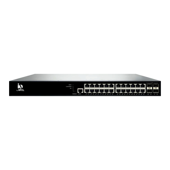
24 Port PoE+ L3
Managed Switch
HSP-IO-24GE4XS-C3PA+
Also Applicable on:
HSP-IO-24GE4XS-C3A+
IO, 24-Port, Non PoE, L3 Managed Switch,
4x1/10G SFP+ Uplinks, Single AC Power Supply
HSP-IO-24GE4XS-C2A+
IO, 24-Port, Non PoE, L2 Managed Switch,
4x1/10G SFP+ Uplinks, Single AC Power Supply
Advertisement
Table of Contents

Related Manuals for HFCL io HSP-IO-24GE4XS-C3PA+


Summary of Contents for HFCL io HSP-IO-24GE4XS-C3PA+
- Page 1 Quick Start Guide 24 Port PoE+ L3 Managed Switch HSP-IO-24GE4XS-C3PA+ Also Applicable on: HSP-IO-24GE4XS-C3A+ IO, 24-Port, Non PoE, L3 Managed Switch, 4x1/10G SFP+ Uplinks, Single AC Power Supply HSP-IO-24GE4XS-C2A+ IO, 24-Port, Non PoE, L2 Managed Switch, 4x1/10G SFP+ Uplinks, Single AC Power Supply...
- Page 2 Advanced GUI with Device Management System High Speed Fiber & Copper Based Backhaul Rich Layer-2 Features With Layer-3 Capabilities...
-
Page 3: Packaging Content
Introduction Thank you for choosing 24 Port managed Switch from HFCL Switching Platform (HSP+). PoE Variants Suitable in an enterprise/telco/campus environment to connect end PoE clients like Wi-Fi AP, CCTV, P2P, P2MP, IoT etc. Non-PoE Variants Suitable to connect Small Cells/BTS, P2P/P2MP etc. -
Page 4: Bracket Assembly
Bracket Assembly Assembly of brackets for Rack mounting is described in the below diagram for 24 Port managed Switch Model. Step 1. Attach the mounting brackets to both sides of the chassis. Insert screws and tighten them with a screwdriver to secure the brackets. Attaching Brackets to the Switch Step 2. -
Page 5: Login Access
Login Access Console Port Access Via Web-GUI Step 1. Connect your PC to the Switch and ensure its IP address is in the same subnet, default IP of the switch is 192.168.1.1/24 Step 2. Open any web browser and enter the URL: http://192.168.1.1 to access the Switch's local web GUI. - Page 6 If your PC is configured correctly, you should see the login page of the switch as shown by the image: Access Via Console The console access to the Switch can be obtained via the console port using the RJ45 interface. An administrator can access the device using Command Line Interface (CLI) with the following console port setting as part of the factory default configuration;...
-
Page 7: Product Specification
Product Specification 24 Port L3 Managed Switch Specifications Capacity Switching: 128 Gbps, Forwarding: 95.232 mpps Port Configuration 24x10/100/1000M RJ45 ports PoE Features PoE Budget - 370W, PoE Configuration and Scheduling Uplink Ports 4x1/10G SFP+ Uplink Ports L3 Features RIP v1/v2, OSPFv2/v3, Static Routing L2 Features Support 4094 VLAN IDs, 32K MAC Table Security... -
Page 8: Led Description
LED Description The LEDs on the front panel provide users with switch status checking and monitoring.There are three types of LEDs as follows: The following table details the functions and descriptions of various LED indicators. Table 1: System LED Color State Description The switch is powered ON correctly. - Page 9 Table 3: Port Status LEDs When Link/Act/Speed Mode LED Lit Color State Description Green The port is enabled and established a link to the connected device, and the connection speed is 1000Mbps Green Blinking The port is transmitting/receiving packets, and the connection speed is 1000Mbps.
-
Page 10: Mode/Reset Button
When PoE Mode LED Lit Color State Description Green The port is enabled and supplying power to the connected device. Amber An abnormal state, such as overload RJ45 status, has been detected in the switch. Ports The port has no active network cable connected, or it is not connected a PoE PD device. -
Page 11: Safety Precautions
Safety Precautions Observe the following safety precautions to avoid damage to the Switch: Do not power the device during installation. Keep away from high voltage cables. Do not power off the unit in the middle of an upgrade process. Do not open the enclosure. - Page 12 | io.hfcl.com Contact Us: 8, Commercial Complex, Masjid Moth, Greater Kailash-II, New Delhi- 110048 HFCL Limited All Rights Reserved. HFCL and io by HFCL are trademarks or registered trademarks of HFCL Ltd. Specifications are subject to change without prior notice.
Need help?
Do you have a question about the io HSP-IO-24GE4XS-C3PA+ and is the answer not in the manual?
Questions and answers