Sign In
Upload
Manuals
Brands
Hologic Manuals
Medical Equipment
Fluent Pro
Hologic Fluent Pro Manuals
Manuals and User Guides for Hologic Fluent Pro. We have
1
Hologic Fluent Pro manual available for free PDF download: Operator's Manual
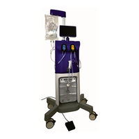
Hologic Fluent Pro Operator's Manual (98 pages)
Fluid Management System
Brand:
Hologic
| Category:
Medical Equipment
| Size: 14 MB
Table of Contents
Table of Contents
5
Introduction to System, Warnings and Precautions
13
Important Operator/User Notes
13
Trademark Notice
13
Manufacturer
13
Indications for Use
13
Intended Users
13
Intended Use Environment
13
Patient Target Group
13
Contraindications
13
Important User Notes
13
Essential Performance
14
Warnings and Precautions
14
Definitions
14
List of Warnings and Precautions
14
System Introduction
15
Introduction to the Fluent Pro Fluid Management System
15
Shipping Contents
16
System Components
16
Figure 1: Front View of System
16
Figure 2: Rear View of System
17
Figure 3: System Launch Screen
18
Figure 4: System Settings Screen
19
Figure 5: System Setup Screen
19
Figure 6: System Confirmation Screen
20
Figure 7: Procedure Screen
20
Figure 8: 360° Handle
22
Fluent Pro Procedure Kit Components
23
Figure 9A: Carton Components
23
Figure 9B: Tray Components
23
Figure 9C: Waste Bag
23
Procedure Setup
25
Moving the System
27
Positioning the System
27
Figure 10: Unlock Wheels
27
Figure 11: Positioning the System
27
Connecting the Power Cord
28
Locking the Wheels
28
Figure 12: Lock Wheels
28
Turning on the Fluent Pro Fluid Management System
29
Configure System Settings (Required for Initial Setup)
29
Figure 13A: Power Button
29
Figure 13B: Launch Screen
29
Figure 14: Settings Screen
29
Setup System
30
Setup Screen
30
Figure 15: Launch Screen
30
Figure 16: Setup Screen
30
Hang Fluid Bag
31
Unpack the Fluent Pro Procedure Kit
31
Figure 17: Setup Step Detected Screen
31
Figure 18: Hang Fluid Bag
31
Figure 19A: Carton and Tray
32
Figure 19B: Carton, Tray and Waste Bag
32
Figure 20: Waste Bag
32
Figure 21: Peel Back Sterile Cover
32
Hang Waste Bag
33
Figure 22A: Out-Flopak Connections
33
Figure 22B: In-Flopak Connections
33
Figure 23: Hang Waste Bag
33
Install In-Flopak
34
Figure 24A: Depress In-Flopak Lever
34
Figure 24B: Slide In-Flopak over Shaft
34
Figure 25: Clamp Tubing and Spike Fluid Bag
34
Install Out-Flopak
35
Figure 26A: Depress Out-Flopak Lever
35
Figure 26B: Slide Out-Flopak over Shaft
35
Figure 27: Connect UBD Suction Connector
35
Figure 28: Connect Waste Bag Connector
36
Figure 29: Setup Screen with All Setup Steps Detected
36
Figure 30: Confirmation Screen
37
Figure 31: Confirmation Screen with Steps Complete
37
Priming the System
38
Figure 32: Initial Prime Screen
38
Figure 33: Unclamp Fluid Bag
38
Figure 34: Open Inflow Stopcock and Unclamp Inflow Tubing
39
Figure 35: Direct Priming Fluid into UBD
39
Figure 36: Initial Prime Screen
40
Figure 37: Air Purge Screen
40
Priming Pause
41
Figure 38: Hysteroscope Calibration Screen
41
Figure 39: End Priming Screen
41
Figure 40: Priming Paused Screen
42
Figure 41: Priming Complete Screen
42
How to Reprime
43
Connecting the Myosure Tissue Device (TRD)
43
Figure 42: Procedure Screen
43
Figure 43: Reprime Screen
43
During Procedure
45
Adjusting the Deficit
47
Figure 44: Procedure Screen
47
Zeroing the Deficit
48
Adjusting Thei
48
Figure 45: Change Deficit Limit Screen
48
Adjusting the Suction
49
Performing the Procedure
49
Figure 46: Connecting the Myosure TRD
49
Figure 47: Change Scope Screen
50
Figure 48: Ready to Prime Screen
51
Figure 49: Priming Complete Screen
51
Ending the Procedure
52
Figure 50: Procedure End Confirmation Screen
52
Figure 51: Recovering Fluid Screen
52
Last Procedure Data
53
Replacing Components
54
Adding the Fluid Bag
54
Figure 52: Last Procedure Data Screen
54
Waste Bag
55
Figure 53: Remove Waste Bag Connector
55
Figure 54: Screw Waste Bag Cap Onto Waste Bag
56
Figure 55: Remove Full Waste Bag
56
Figure 56: Install Waste Bag Connector
56
Tissue Trap
57
Figure 57: Open Tissue Trap Canister Lid
57
After Procedure
59
Disassembly and Disposal
61
Yo Sure Tissue Removal Device Athology
61
Figure 58: Disconnecting the Myosure TRD
61
Dispose of Waste Materials
62
Figure 59: Remove Waste Bag Connector
62
Figure 60: Screw Waste Bag Cap Onto Waste Bag
62
Disassemble the
63
Under -Buttocks Drape Hysteroscope
63
Fluent Pro I N -Flo Pak
63
Figure 61: Remove Full Waste Bag
63
Figure 62: Disconnect UBD
63
Shutdown and 4.2 Cleaning the Fluentp
64
Fluent Pro out -Flo Pak
64
Fluid Management System
64
Storing the System
64
Troubleshooting
67
Help
69
Help Screen Menu
69
Figure 63: Help Icon Location
69
Figure 64: Help Screen Menu
69
Help with Setup
70
Riming
70
Figure 65A: Setup Help Menu
70
Figure 66: Priming Help Screen
70
Figure 65B: Additional Setup Help Menu
70
Help During the
71
Figure 67: Procedure Running Help Screen
71
Figure 68: Procedure End Help Screen
71
Troubleshooting
72
Uction
72
Figure 69: System Restarted Screen
72
Loss of Suction 5.3.3 Inadequate S 5.3.4 Poor Visibility
73
Poor Uterine
73
Tissue Resection
73
Fluid Deficit Difficulty
73
System Frozen
74
Limit
75
Table 1: Real-Time Display, Notifications and Troubleshooting
75
Table 2: Real-Time Display, Alerts and Troubleshooting
76
Figure 70: System Fault Screen
77
Table 3: Real-Time Display, System Faults
78
Supplementary Information
79
Annual Inspection
81
Scale Calibration Check
81
Figure 71: Scale Calibration Check Overview Screen
81
Figure 72: Scale Calibration Check, Part 1 Screen
82
Figure 73: Scale Calibration Check, Scales Zeroed Screen
82
Figure 74: Scale Calibration Check, Part 2 Screen
83
Alibration Check
84
Figure 75: Pressure Calibration Check Overview Screen
84
Figure 76: Pressure Calibration Check Steps, Part 1
84
Figure 77: Pressure Calibration Check Steps, Part 2
85
Figure 78: Begin Purge for Pressure Calibration Check
85
Figure 79: Stop Purge for Pressure Calibration Check
86
Figure 80: Performing Pressure Calibration Check
86
Technical Specifications
87
Table 4: Technical Specifications
87
Power Cord Safety
88
Electromagnetic Compatibility
88
Table 5: Electromagnetic Emissions Guidance
88
Table 6: Electromagnetic Immunity Guidance
89
Emissions Guidance and M Immunity Guidance and M Separation Distances
91
Table 7: Guidance and Manufacturer's Declaration - Electromagnetic Immunity
91
Table 8: Recommended Separation Distances
91
Console Disposal
92
Procedure Kit Storage
92
Procedure Kit Disposal
92
Disposables Anda
92
Ccessories
92
Information
92
Table 9: Disposables and Accessories
92
Figure 81: Preventative Maintenance Due Date
93
Warranty Information
93
Nformation
94
Complaints R 6.9.5 Contacting H 6.10 Symbol Glossary
94
Eporting
94
Ologic Technical Support
94
Table 10: Symbols
94
Glossary
96
Advertisement
Advertisement
Related Products
Hologic Fluoroscan InSight FD Mini C-arm
Hologic Faxitron Core
Hologic Faxitron CT
Hologic Faxitron Path
Hologic Fluoroscan Insight FD
Hologic Rapid fFN 10Q
Hologic FLUOROSCAN InSight-FD Mini C-arm
Hologic 3Dimensions
Hologic Acessa ProVu
Hologic Affirm
Hologic Categories
Medical Equipment
Laboratory Equipment
Server
Control Systems
Rfid Systems
More Hologic Manuals
Login
Sign In
OR
Sign in with Facebook
Sign in with Google
Upload manual
Upload from disk
Upload from URL