Table of Contents
Advertisement
Quick Links
Advertisement
Table of Contents

Related Manuals for Lumel NC12


Summary of Contents for Lumel NC12
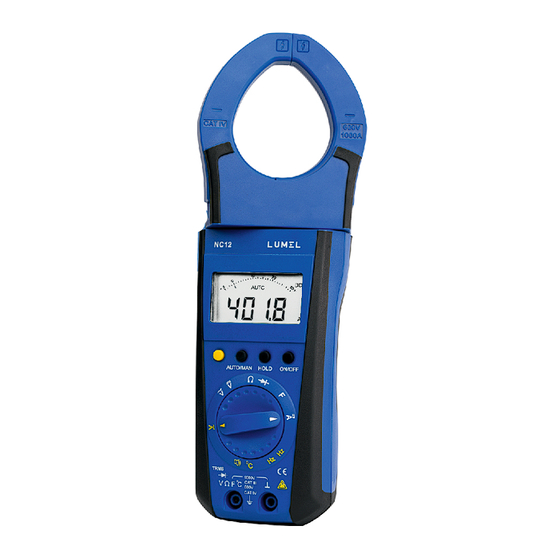
- Page 1 AC/DC CLAMP-ON METER 1000 A/ 300 A NC12 USER’S MANUAL...
- Page 3 (22) (20) (21)
-
Page 4: Table Of Contents
Liquidcrystaldisplay (11) Display for the selected function ON/OFF push button (12) Display for the unitof Push button for data hold measuredquantity. And MIN/MAX storagefunctions (13) Over range indication for positiveanalogrange. Push button for manual range (14) Pointerforanalogindication. selection (15) Scalefor analogindication Multifunctionpushbutton (16) Over range indication for negativeanalogrange. -
Page 5: Introduction
1. Introduction: ClampMeter. Thankyouvery much forselecting Weare leadingmanufacturer of Electrical a n d Electronicsstate-of-art measuring instruments. And DIN43751. These clamp meters are Manufactured as per IS.13875 2. Safety features and safety precautions You have chosen a Clamp meter which provides you a very high degree 300A/1000A tested of safety. -
Page 6: Switching The Clampmeter "On
Meaning of categories and their signifi canceper IEC61010- CAT I: Measurements in electrical circuits which are not directly connected to the mains: for example electrical systems in motor vehicles and aircraft, batteries etc. circuits Measurements in electrical w hich are electrically connected to the low-voltage mains:with plugs, e.g. -
Page 7: Automatic Turn-Off
Switching the meter “ON" Press the"ON/OFF"push button (2). Switch - “ON"is Acknowledged by a sound Signal. As long as you Keep the push button pressed, all segments of the LCD will appear.The LCD is shown behind over page After the push button is released, the meter is ready for operation. Note: Electric discharges and high-frequency Influence may caus e incorrect... -
Page 8: Liquid Crystal Display
30 nF 300 nF 3 μF 30 μF 30 nF... 300 Hz 3 KHz 30 KHz 100 KHz 300 Hz... 300A 1000A 300A... A , A NC12Clamp 1000A 30A... 300A 300A A , A NC12Clamp 5. Liquid crystal display 5.1 Digital display The digital display(9)shows the measured value with correc Tlocation of decimal Point and sign.The selected measuring Unit(12) and the func tion(11) -
Page 9: Data "Hold" Facility
6. Data “HOLD” facility The HOLD function allows To automatically hold the measured values. The meter holds The measured value On the Digital display wit h a sound Signal and displays “ HOLD ” on LCD display (10). The probes or clamp Measuring point And the measured value Can now be removed from the On the digital display (9)can be read.The analog indication... - Page 10 Meter acknowledgement Display Meas- Measured Function DATA Meas. Values uring Sound MIN/MAX MIN/MAX Value MINandMAX ranges Signal digital 2xShort, actual 30mV/ meas- Stored 300mV Ω , ,% Activateand ured flash Store value 1xshort stored StorageContinued value short inthebackground, Storeand Ω , ,% stored newMIN/MAX.
-
Page 11: Voltage Measurement On Electrical System Up To1000V
Voltagemeasurement AUTO Voltage measurement on electrical systems up to 1000V With the KS30 measuring adapter AUTO... -
Page 12: Voltage Measurement
8. Voltage measurement According to the voltage to be measured, set The function sel e ctor Switch(6) to V “ socket should be Connect the test leads as Shown. The “ connected to the lowest potential ground available. Notes: The 30 mV And 300 mV measuring ranges can only be selected manuallywiththe “AUTO/MAN”... - Page 13 Resistance measurement RISH Clamp 1000A HOLD AUTO KΩ AUTO/MAN HOLD ON/OFF Diode Test Forwarddirection Reversedirection RISH Clamp 1000A RISH Clamp 1000A AUTO AUTO HOLD ON/OFF AUTO/MAN HOLD ON/OFF AUTO/MAN Continuity Test RISH Clamp 1000A RISH Clamp 1000A AUTO AUTO AUTO/MAN HOLD ON/OFF AUTO/MAN...
-
Page 14: Resistance Measurement
9. Resistance measurement Verify that the device under test is electrically dead. External voltages Would falsify the measured result! Set the function selector switch(6) to “Ω”. Connect the device under test as shown. Ω Zero adjustment on the 30 measuring range When measuring small resistance Values on the 30Ω... -
Page 15: Temperature Measurement
11. Temperature measurement Allows you to measure Temperature 1 2 Clamp 300A/ 1000A AC-DC with Pt100 and Pt1000 temperature sensors in the range from- 200( -100) C...+850 Set the function selector switch(6) to"Ω " Connect the sensor to the two terminals. Briefly press the yellow Multifunction push button(5). -
Page 16: Frequency Measurement
Zero adjustment on the 30 nF measuring range When measuring small capacitrance values on the 30 nF range, the internal resistance of the multimeter and the capacitrance of the leads can be eliminated by zero adjustement. Connect the test leads to the meter without device under test. Briefly press the yellow multi-function pushbutton (5) diplaying"00.00"(+1 digit) on the LCD and by a flashing decimal point.The capacitance measured at the instant the pushbutton is pressed is used as reference value (max.200 digits). -
Page 17: Currentmeasurement
15. Currentmeasurement 1000A Current Up to 1000A, in two ranges can measure Clamp NC 1 2 300A can measure I.e. 300.0A and 1000A. Where as current up to 300A in Two ranges i.e.30.00 A and 300.0 A. One of the two range scan be selected manually with AUTO/MAN Key. To measure the current through a cable, push the trigger (21) to open the jaws and clamp the jaws around the cable as shown in Figure a and figure b. - Page 18 Unique design for safety and comfort Rotary mechanism for clamp jaws: n conventional clamp meters display, keys and clamp jaws are in the same plane. When current measurement is to be done on vertical bus bars, over head cables, cables in congested places user connect the clamp meter but the keys and display may not be visible, hence not able to take the readings or operate the keys.
-
Page 19: Emptypositions
Normally, it is difficult to access the middle busbar for current measurement. With Rotary mechanism for clamp jaws it is easy to access middle bus bar, " " while keeping display and keys facing towards the user as shown in figure d on previous page. -
Page 20: Specifications
17.Specifications Overload Intrinsicerrorof Meas- capacity1) digitaldisplay Reso- urement MeasuringRange Inputimpedance (...%ofrdg. lution Function +...digits)at Overload Overload Value reference duration conditions 10 mV >10G Ω// < 40pF 30.00 mV 0.5+3 1000V 100 mV 300.0 mV >10G Ω// < 40pF 0.5+3 11M Ω// < 40pF 3.000 0.25 + 1 Contin-... -
Page 21: Reference Conditions
3VU=1.5V 100V eff/rms... eff/rms 30VU=15V ...300V eff/rms eff/rms 300VU=150 ...1000V eff/rms eff/rms 5) On the range 3V , Square wave signal positive on oneside 5...1 5V, F=const.,not 163.84Hz or integral multiple Referenceconditions + 23 C +2K Ambient temperature : 45% ... 55 % RH Relative humidity: 45Hz ...65 Hz Frequency of measured... - Page 22 Variation Measured +(...%ofrdg.+...digits) Influence quantity/ RangeofInfluence quantity Measuringrange 30/300mV 1.0+3 3...300V 0.15+1 1000V 0.2+1 0.4+2 Ω 0.15 + 2 Ω 0.25+2 0.15+1 Ω - Ω T emperature 1.0+1 Ω - 200 ... + 200 0.5 +2 C...+40 0.5+2 +200...+850 0.1 x specified accuracy +10 2.0+3 >65Hz...400Hz Frequency...
- Page 23 Display Liquid crystal display section (52mmx38mm) with analog ind Ication and digital Display and wit hdisplay of the Unit of measured quantity, function and Various special functions. Analog: Indication LCD Scale with pointer Scale length 55mm Graduation 5...0... 30 with 29 scale divisionson 0...30 with 25 Scale divisions on all other ranges Polarity indication With automatic change-over...
-
Page 24: Maintenance
Responsetime (aftermanualrangeselection) Responsetime Transientresponsefor Measuredquantity/ stepfunctionofthe ofanalog ofdigital measuringrange measuredquantity indication display from 0 to 80 % 0.7s 1.5s ofupperrangelimit 30Ω...3MΩ 1.5s from 0 to 50% 30MΩ Of upperrange limit 0.7s 1.5s Max.1...3s µF, 300 Hz,3 KHz from to50% Max.2s ofupperrangelimit 30,100 KHz Max.0.7s... -
Page 25: Periodic Check-Up
Attention! Disconnect the instrument from the measuring circuit Before opening battery cover to replace the batteries. Replacing the battery Place the clamp meter on its face. Loosen the screw of battery cover Which is a trearbottom side of meter. Remove battery cover by Sliding it to bottom side. - Page 26 NOTE...
- Page 28 LUMEL S.A. ul. Sulechowska 1, 65-022 Zielona Góra, POLAND tel.: +48 68 45 75 100, fax +48 68 45 75 508 www.lumel.com.pl Export department: tel.: (+48 68) 45 75 139, 45 75 233, 45 75 321, 45 75 386 fax.: (+48 68) 32 54 091 e-mail: export@lumel.com.pl...
Need help?
Do you have a question about the NC12 and is the answer not in the manual?
Questions and answers