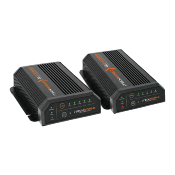
Summary of Contents for iTechworld iTECHDCDC25
- Page 1 USER GUIDE iTECHDCDC25/40 INTELLIGENT BATTERY CHARGERS PATENT PENDING © 2024, iTechworld Pty Ltd. All rights reserved. Ver 1.0...
- Page 2 QUICK START GUIDE Step 1. Connect the auxiliary battery to the iTECHDCDC charger output via a fuse. Step 2 Connect the cranking battery to the iTECHDCDC charger input via a fuse. Step 3. Connect the solar panels to the iTECHDCDC charger solar input via a fuse. Step 4.
-
Page 3: Table Of Contents
CONTENTS Product Overview Key Features Package Contents Display Panel Battery Charging Profile Solar Priority LED Charge Indicator Unit Operation Fault Resolution Installation Install Location Selection of Cable Size Wiring Typical Setup Fuse Specifications Specifications Safety Precautions Contact Us Back Page... -
Page 4: Product Overview
• Inbuilt low-voltage, over-voltage, over-temperature and reverse polarity • protection. Isolates the cranking battery from the auxiliary battery. • Automatically brings iTechworld lithium batteries out of safe mode. • IP67 rated waterproof. • Package Contents Colour Coded Anderson iTECHDCDC25 or 40... -
Page 5: Display Panel
SOLAR PRIORITY The iTECHDCDC40 and iTECHDCDC25 are set up with alternator priority as default, as the power from solar can be very unstable, which thus affects charge efficiency. If you prefer solar charging regardless of its charging efficiency, or your auxiliary battery has a small load connected and you want to use solar charging as much as possible, you can enable the “Solar Priority”... -
Page 6: Led Charge Indicator
2 minutes for the charger to “wake” and begin to charge. The iTECHDCDC charger will start to charge from solar input if the panel supply voltage is above 16V and outputting at least 25W (1.5 Amps). iTECHDCDC25/40 Operation Input Turn On... -
Page 7: Fault Resolution
FAULT RESOLUTION Alternator Battery Fault LED Resolution Solar LED Explanation Type LED Low voltage detected Check alternator input Quick flash Quick flash at alternator input voltage Low voltage detected Check solar input voltage Quick flash Quick flash at solar input Low voltage detected Check both alternator Quick flash... -
Page 8: Selection Of Cable Size
(4AWG) Ignition 0.5mm2 (20AWG) 0.5mm2 (20AWG) 0.5mm2 (20AWG) iTechworld strongly advises that a properly trained / qualified individual conducts this task. Failure to establish a secure connection could result in a short circuit, potentially leading to fire and property damage. -
Page 9: Wiring
For wire extensions, it is advisable to utilise soldered butt splice connectors. This ensures minimal resistance in the connections. The optimal approach is to crimp both ends of the connector, followed by soldering both sides of the connector. Once the connection is secured, it is crucial to employ heat shrink tubing to protect the connections and prevent any short circuits. -
Page 10: Typical Setup
TYPICAL SETUP... -
Page 11: Fuse Specifications
FUSE SPECIFICATIONS FUSE SPECIFICATIONS It is essential to install all recommended fuses in series within the circuit. Bolt-down fuses are the preferred choice as they guarantee a low-resistance connection. In contrast, self-resetting circuit breakers are not recommended as they may trip prematurely due to the heat generated by the current fl owing through the wires. -
Page 12: Specifications
SPECIFICATIONS General Rating Model iTECHDCDC25 iTECHDCDC40 Vehicle input voltage 9V - 32V Solar input voltage 10V - 32V Max input current Input fuse rating Continuous output current Up to 25A Up to 40A Output fuse rating Minimum aux battery charge start voltage Standby current <10mA... -
Page 13: Safety Precautions
Disclaimer: While iTechworld has taken every precaution to ensure the accuracy of the contents of this user guide, iTechworld assumes no responsibility for any errors or omissions. Furthermore, all specifications and functionality may change at any time without notice. - Page 14 WARNING: Please use the fuses and wires recommended in this user guide, otherwise it may result in damage to the inverter, a risk of electrical shock, fire, death or serious injury. WARNING: Ensure the continuous output current of the charger does not exceed the battery’ s recommended maximum charging current.
-
Page 16: Contact Us
1300 483 249 service@itechworld.com.au www.itechworld.com.au When it comes to energy storage and creation at iTechworld, we take pride in being one of the biggest names in the industry. Based in Australia, we are a family-owned and operated business. With many more innovative products on the horizon we are committed to constantly raising the bar to provide bigger and better benefi ts to all our customers Australia-wide.


Need help?
Do you have a question about the iTECHDCDC25 and is the answer not in the manual?
Questions and answers