Craftmade Garrick GAR56 Installation Manual
Hide thumbs
Also See for Garrick GAR56:
- Installation manual (36 pages) ,
- Installation manual (36 pages)
Table of Contents
Advertisement
Quick Links
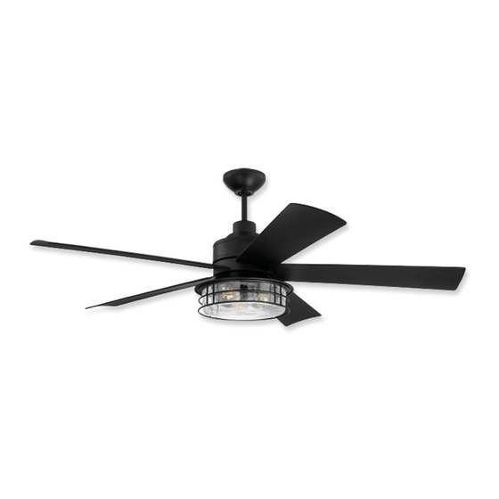
Garrick
Installation Guide
For Model:
GAR56
For
Wet Location
E192641
net weight of fan: 31.09 lb (14,1 kg)
READ THESE INSTRUCTIONS AND
SAVE THEM FOR FUTURE USE
Table of Contents:
Safety Tips. pg. 2
Unpacking Your Fan. pg. 3
Parts Inventory. pg. 3
Installation Preparation. pg. 4
Hanging Bracket Installation. pg. 4
Fan Assembly. pgs. 5 - 6
Wiring. pg. 7
Canopy Assembly. pg. 8
Blade Assembly. pg. 8
Light Kit Assembly. pg. 9
Handheld Remote Control Assembly. pg. 10
Remote/Wall Control Operation. pg. 11
Testing Your Fan. pg. 11
Troubleshooting. pg. 12
Warranty. pg. 12
Parts Replacement. pg. 12
page 1
PRINTED IN CHINA
Advertisement
Table of Contents

Related Manuals for Craftmade Garrick GAR56


Summary of Contents for Craftmade Garrick GAR56
-
Page 1: Table Of Contents
READ THESE INSTRUCTIONS AND SAVE THEM FOR FUTURE USE Garrick Installation Guide For Model: GAR56 Table of Contents: Safety Tips. pg. 2 Unpacking Your Fan. pg. 3 Parts Inventory. pg. 3 Installation Preparation. pg. 4 Hanging Bracket Installation. pg. 4 Fan Assembly. -
Page 2: Safety Tips
SAFETY TIPS. WARNING: To reduce the risk of electrical shock, turn off the electricity to the fan at the main fuse box or circuit panel before you begin the fan installation or before servicing the fan or installing accessories. READ ALL INSTRUCTIONS AND SAFETY INFORMATION CAREFULLY BEFORE INSTALLING YOUR FAN AND SAVE THESE INSTRUCTIONS. -
Page 3: Unpacking Your Fan
1. Unpacking Your Fan. Carefully open the packaging. Remove items from Styrofoam inserts. Remove motor housing and place on carpet or Styrofoam to avoid damage to finish. Do not discard fan carton or Styrofoam inserts should this fan need to be returned for repairs. Check against parts inventory that all parts have been included. -
Page 4: Installation Preparation
3. Installation Preparation. blade edge To prevent personal injury and damage, ensure inches 7 feet that the hanging location allows the blades a (2.13 m) (76 cm) clearance of 7 feet (2.13m) from the floor and 30in. (76cm) from any wall or obstruction. This fan is suitable for room sizes up to 400 square 12ft. -
Page 5: Fan Assembly. Pgs
5. Fan Assembly. set screw stop pin Remove hanging ball from downrod provided by loosening set screw on hanging ball. Lower hanging hanging ball ball and remove stop pin and then slide hanging ball off of the downrod. [Refer to diagram 1.] diagram 1 Loosen yoke set screws and nuts at top of motor housing. - Page 6 5. Fan Assembly. (cont.) Remove electrical tape from electrical wiring safety cable and thread each of the wires through a different hole in the weatherproof hanging weatherproof ball cover. Pull weatherproof hanging ball hanging ball cover cover down securely over hanging ball (on electrical wiring downrod).
-
Page 7: Wiring
6. Wiring. ground (green WARNING: Turn off circuit breakers to current fixture from or bare) white supply wire breaker panel and be sure switch is turned to the OFF position. black supply wire ground (green CAUTION: Be sure outlet box is properly grounded and that or bare) a ground wire (GREEN or Bare) is present. -
Page 8: Canopy Assembly
7. Canopy Assembly. antenna Locate 2 screws on underside of hanging bracket and remove screw closest to the open hanging bracket receiver end of the hanging bracket. Partially loosen the other screw. Lift canopy to hanging bracket. Place rounded part of slotted hole in canopy screw over loosened screw in hanging bracket and push up. -
Page 9: Light Kit Assembly
9. Light Kit Assembly. Remove 1 screw from motor plate on underside of motor housing and partially loosen the other 2 screws. Align slotted holes in fitter plate with loosened screws in motor plate, allowing motor molex connectors to come through center housing hole in fitter plate. -
Page 10: Handheld Remote Control Assembly
10. Handheld Remote Control Assembly. remote IN ORDER TO USE THE HANDHELD REMOTE CONTROL, CONTINUE WITH SECTION 10 for remote control control assembly instructions. If you have already installed the cover wall control but do not wish to use the handheld remote control, proceed to Section 11. -
Page 11: Automated Learning Process./Activating Code
11. Automated Learning Process./Activating Code. CAUTION: The wall and/or handheld remote control can be programmed to multiple receivers or fans. If this is not desired, turn wall switch off to any other programmable receiver or fan. Restore electrical power and then, if using wall control, set slider switch on wall control to the ON position. -
Page 12: Troubleshooting
Service at 1-800-486-4892 to arrange for return of fan. direction. Return fan, shipping prepaid, to Craftmade. We will repair 3. Check to be sure wall control (optional use) is wired or ship you a replacement fan, and we will pay the return properly.
Need help?
Do you have a question about the Garrick GAR56 and is the answer not in the manual?
Questions and answers