Table of Contents
Advertisement
Available languages
Available languages
Quick Links
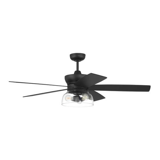
Gibson
Installation Guide
For Model:
GBN52
WARNING:
DC Motor will not
operate until blades
are installed
net weight of fa
net weight of fan: 17.2 lb (7.8 kg)
READ THESE INSTRUCTIONS AND
AND SAVE THEM FOR FUTURE USE
Table of Contents:
Safety Tips. pg. 3
Unpacking Your Fan. pg. 4
Parts Inventory. pg. 4
Installation Preparation. pg. 5
Hanging Bracket Installation. pg. 5
Fan Assembly. pgs. 6 - 7
Wiring. pg. 7
Canopy Assembly. pg. 8
Blade Assembly. pg. 8
Light Kit Assembly. pg. 9
Remote Control Operation. pg. 11
Smart Ceiling Fan Wi-Fi Control. pg. 12
Testing Your Fan. pg. 13
Troubleshooting. pg. 14
Warranty. pg. 14
page 1
PRINTED IN CHINA
Advertisement
Chapters
Table of Contents

Subscribe to Our Youtube Channel
Related Manuals for Craftmade Gibson GBN52


Summary of Contents for Craftmade Gibson GBN52
-
Page 1: Table Of Contents
READ THESE INSTRUCTIONS AND AND SAVE THEM FOR FUTURE USE Gibson Installation Guide For Model: Table of Contents: GBN52 Safety Tips. pg. 3 Unpacking Your Fan. pg. 4 Parts Inventory. pg. 4 Installation Preparation. pg. 5 Hanging Bracket Installation. pg. 5 WARNING: Fan Assembly. - Page 2 Activating Your New Smart Fan; Downloading the Bond Home App • Using your smart device, navigate to the application store (Apple App store or Google Play), download the free Bond Home app and create account. • Ensure the fan and receiver are receiving power from the house supply using the remote control to turn the fan and light ON and OFF.
-
Page 3: Safety Tips
(2) this LED light kit must accept any interference received, including interference that may cause undesired operation. Distributed by: Craftmade, 3901 S. 20th Avenue, DFW Airport, TX 75261; 1-800-486-4892 NOTE: The important safety precautions and instructions appearing in the manual are not meant to cover all possible conditions and situations that may occur. -
Page 4: Unpacking Your Fan
1. Unpacking Your Fan. Carefully open the packaging. Remove items from Styrofoam inserts. Remove motor housing and place on carpet or Styrofoam to avoid damage to finish. *The motor stabilization pieces may be dicarded at this time. Do not discard fan carton or Styrofoam inserts should this fan need to be returned for repairs. -
Page 5: Installation Preparation
3. Installation Preparation. blade edge To prevent personal injury and damage, ensure inches that the hanging location allows the blades a (76 cm) 7 feet clearance of 7 feet (2.13m) from the floor and (2.13 m) 30in. (76cm) from any wall or obstruction. This fan is suitable for room sizes up to 400 square 12ft. -
Page 6: Fan Assembly. Pgs
stop pin set screw 5. Fan Assembly. Remove hanging ball from downrod provided by loosening set screw on hanging ball. Lower hanging hanging ball ball and remove stop pin and then slide hanging ball off of the downrod. [Refer to diagram 1.] diagram 1 Loosen yoke set screws and nuts at top of motor housing. -
Page 7: Wiring
5. Fan Assembly. (cont.) wood ceiling joist With the hanging bracket secured to the outlet box and able to safety cable support the fan, you are now ready to hang your fan. Grab the loop fan firmly with two hands. Slide downrod through opening in hanging bracket and let hanging ball rest on the hanging bracket. -
Page 8: Canopy Assembly
7. Canopy Assembly. Locate 2 screws on underside of hanging bracket and remove screw closest to the open end of the hanging hanging bracket. Partially loosen the other screw. bracket Lift canopy to hanging bracket. Place rounded part of slotted hole in canopy screw over loosened screw in hanging bracket and push up. -
Page 9: Light Kit Assembly
9. Light Kit Assembly. motor housing Remove 1 screw from motor plate on underside of motor housing and partially loosen the other 2 screws. Align slotted holes in center of shade fitter with loosened screws in motor plate, allowing molex connections from motor plate motor housing to come through hole in middle of shade fitter. -
Page 10: Automated Learning Process./Activating Code
10. Automated Learning Process./Activating Code. CAUTION: The remote control transmitter can be programmed to multiple receivers or fans. If REMOTE CONTROL this is not desired, turn wall switch off to any TRANSMITTER other programmable receiver or fan. (back side) Remove battery cover on back side of remote control transmitter. -
Page 11: Remote Control Operation
11. Remote Control Operation. REMOTE CONTROL TRANSMITTER I I I 1--Fan SPEED buttons: Use to control fan speeds 1-6 2--Fan OFF button: Use to turn the fan off 3--REVERSE function button: Use to control direction of fan rotation 4--LIGHT button: Use to control light IMPORTANT: The Automated Learning Process takes approximately 5 minutes to complete. -
Page 12: Smart Ceiling Fan Wi-Fi Control
12. Smart Ceiling Fan Wi-Fi Control. (Optional) Without Wi-Fi activation, you will not enjoy the expanded features and functionality of your ceiling fan: Breeze speed setting, Creating Schedules and Voice Activation. To enjoy all the potential of your new device, refer to the following steps to complete Smart setup. -
Page 13: Testing Your Fan
13. Testing Your Fan. It is recommended that you test fan before finalizing installation. Restore power from circuit box and wall switch (if applicable). Test fan speeds with the different fan speed buttons (I - VI) on remote control transmitter. Test the light ON/OFF function by pressing button. -
Page 14: Troubleshooting
Troubleshooting. Warranty. CRAFTMADE LIMITED LIFETIME WARRANTY: WARNING: Failure to disconnect power supply CRAFTMADE warrants this fan for use as intended under prior to troubleshooting any wiring issues may the following provision: CRAFTMADE will replace any result in serious injury. fan which has faulty performance due to a defect in material or workmanship or fails to operate satisfactorily Problem: Fan fails to operate. - Page 15 LEER ESTAS INSTRUCCIONES Y GUARDARLAS PARA UTILIZACIÓN FUTURA Gibson Guía de instalación Para modelo: Índice de materias: GBN52 Sugerencias de seguridad. Pág. 3 Desempaquetado del ventilador. Pág. 4 Inventario de piezas. Pág. 4 Preparación para la instalación. Pág. 5 Instalación del soporte de montaje. Pág. 5 ADVERTENCIA: Ensamblaje del ventilador.
- Page 16 Activar su nuevo ventilador inteligente; Descargar la aplicación Bond Home • Con su dispositivo inteligente, navegar en la tienda de aplicaciones (Apple App store o Google Play), descargar la aplicación gratis Bond Home y crear una cuenta. • Asegurarse de que el ventilador y el receptor estén recibiendo la corriente del suministro de fuerza eléctrica de la casa usando el control remoto para ENCENDER y APAGAR el ventilador y la luz.
-
Page 17: Sugerencias De Seguridad. Pág
(2) este juego de luz LED tiene que aceptar cualquier interferencia recibida, inclusive interferencia que puede producir un funcionamiento indeseado. Distribuido por: Craftmade, 3901 S. 20th Avenue, DFW Airport, TX 75261; 1-800-486-4892 NOTA: No se debe concluir que las precauciones de seguridad importantes e instrucciones en este manual van a abarcar todas las condiciones y situaciones posibles que puedan ocurrir. -
Page 18: Desempaquetado Del Ventilador. Pág
1. Desempaquetado del ventilador. Abrir el empaque cuidadosamente. Sacar los artículos del embalaje. Sacar el motor y ponerlo en una alfombra o en el embalaje para evitar rayar el acabado. *Se pueden desechar las piezas de estabilización del motor en este momento. Guardar la caja de cartón o el empaquetamiento original en caso de que tenga que mandar el ventilador para alguna reparación. -
Page 19: Preparación Para La Instalación. Pág
borde 3. Preparación para la instalación. del aspa Para prevenir daño corporal y otros daños, estar seguro 76 cm de que el lugar en donde va a colgar el ventilador le 2,13 m pulg.) permite un espacio libre de 2,13 m (7 pies) entre las (7 pies) puntas de las aspas y el piso y 76 cm (30 pulg.) entre las aspas y cualquier pared u otra obstrucción. -
Page 20: Ensamblaje Del Ventilador. Págs
5. Ensamblaje del ventilador. perno de tope tornillo de fijación Quitar la bola que sirve para colgar del tubo provisto aflojando el tornillo de fijación de la bola que sirve para bola que sirve colgar. Bajar la bola que sirve para colgar y sacar el para colgar perno de tope y luego quitar la bola que sirve para colgar deslizándola. -
Page 21: Instalación Eléctrica. Pág
5. Ensamblaje del ventilador. (cont.) viga de Ya que esté sujetado el soporte de montaje a la caja de salida y madera capaz de apoyar el ventilador, usted está listo para colgar el bucle del cable ventilador. Agarrar el ventilador firmemente con las dos manos. de seguridad Deslizar el tubo por la abertura del soporte de montaje y dejar que se detenga la bola en el soporte de montaje. -
Page 22: Colocación De La Cubierta Decorativa. Pág
7. Colocación de la cubierta decorativa. Localizar los 2 tornillos en la parte inferior del soporte de montaje y quitar el tornillo que está localizado más cerca del extremo abierto soporte de montaje del soporte de montaje. Aflojar parcialmente el otro tornillo. Elevar la cubierta decorativa hasta el soporte de montaje. -
Page 23: Instalación Del Juego De Luz. Pág
9. Instalación del juego de luz. bastidor Quitar 1 tornillo de la placa del motor en del motor el lado inferior del bastidor del motor y aflojar parcialmente los otros 2 tornillos. Alinear los agujeros con ranura de en medio del conector para la pantalla con placa del los tornillos aflojados en la placa del motor, motor... -
Page 24: Proceso De Aprendizaje Automático./ El Activar El Código. Pág
10. Proceso de aprendizaje automático./ El activar el código. TRANSMISOR DEL PRECAUCIÓN: Se puede programar el transmisor del CONTROL REMOTO control remoto para usar con varios receptores o (parte de atrás) ventiladores. Si no desea hacer esto, apagar el interruptor de cualquier otro receptor o ventilador programable. -
Page 25: Funcionamiento Del Control Remoto.pág
11. Funcionamiento del control remoto. TRANSMISOR DEL CONTROL REMOTO I I I 1--Botones de VELOCIDAD del ventilador: usar para controlar la velocidad del ventilador de 1- 6 2--Botón de APAGADO del ventilador: usar para apagar el ventilador 3--Botón de REVERSA: usar para controlar la dirección de la rotación del ventilador 4--Botón de ILUMINACIÓN: usar para controlar la luz... -
Page 26: Control Wi-Fi Para Ventilador De Techo Inteligente. Pág
12. Control Wi-Fi para ventilador de techo inteligente. (Opcional) Si no se activa el Wi-Fi, no podrá contar con las características y funcionalidades ampliadas de su ventilador de techo: configuración de velocidad de brisa, crear horarios y activación por voz. Para disfrutar de las posibilidades de su nuevo ventilador, consultar los siguientes pasos para terminar la configuración inteligente. -
Page 27: Verificación Del Funcionamiento Del
13. Verificación del funcionamiento del ventilador. Se le recomienda poner el ventilador a prueba antes de terminar la instalación. Regresar la corriente de electricidad en el cortacircuitos y el interruptor de pared (si se aplica). Verificar las velocidades del ventilador con los diferentes botones de velocidad (I - VI) en el transmisor del control remoto. -
Page 28: Localización De Fallas. Pág
Problema: El ventilador no funciona. satisfactoriamente a causa del uso normal. Comunicarse Soluciones: con el Servicio al cliente de Craftmade al 1. Inspeccionar el interruptor de pared del ventilador. 1-800-486-4892, opción 1 o por correo electrónico a 2. Verificar la instalación eléctrica del ventilador.
Need help?
Do you have a question about the Gibson GBN52 and is the answer not in the manual?
Questions and answers
GBN52 craft made ceiling fan with light. It has been working now for 3 weeks. The Light works but fan won’t. I go through the set reset and fan and light both work. The the fan won’t come on with remote
If the light works but the Craftmade GBN52 ceiling fan is not turning on with the remote, the remote may not be properly synchronized with the fan. The fan functions require correct synchronization to operate. Also, the fan must be set to LOW before using the reverse function. If synchronization does not resolve the issue, refer to the "Troubleshooting" section before contacting customer service.
This answer is automatically generated