
Related Manuals for H3C CPE5100


Summary of Contents for H3C CPE5100
- Page 1 H3C CPE5100 5G Customer Premises Equipment Installation Guide New H3C Technologies Co., Ltd. http://www.h3c.com Document version: 6W100-20240626...
- Page 2 The information in this document is subject to change without notice. All contents in this document, including statements, information, and recommendations, are believed to be accurate, but they are presented without warranty of any kind, express or implied. H3C shall not be liable for technical or editorial errors or omissions contained herein.
- Page 3 Preface H3C CPE5100 5G Wireless Data Terminal Installation Guide describes the installation workflow, pre-installation preparation, device installation,cable connection, post-installation check, initial login to the local network management web, and device maintenance for the CPE5100. This preface includes the following topics about the documentation: •...
- Page 4 Convention Description Folder. Symbols Convention Description An alert that calls attention to important information that if not understood or followed WARNING! can result in personal injury. An alert that calls attention to important information that if not understood or followed CAUTION: can result in data loss, data corruption, or damage to hardware or software.
-
Page 5: Documentation Feedback
It is normal that the port numbers, sample output, screenshots, and other information in the examples differ from what you have on your device. Documentation feedback You can e-mail your comments about product documentation to info@h3c.com. We appreciate your comments. -
Page 6: Table Of Contents
Contents 1 Installation flowchart ················································································ 1-1 2 Preparing for installation ·········································································· 2-1 Safety recommendations ································································································································ 2-1 General safety recommendations ··········································································································· 2-1 Electricity safety ······································································································································ 2-1 Moving safety ·········································································································································· 2-1 ESD prevention ······································································································································· 2-2 Working at heights ·································································································································· 2-2 Examining the installation site ························································································································· 2-3 Temperature and humidity ······················································································································... - Page 7 9 Managing the device through Cloudnet···················································· 9-1 Downloading and installing the Cloudnet app ································································································· 9-1 Logging in to Cloudnet ···································································································································· 9-1...
-
Page 8: Installation Flowchart
Installation flowchart The device installation process is as shown in Figure1-1. Figure1-1 Installation flowchart Start Pre-installation preparation Install device to the specified position Connect cables Install antennas Install the SIM card Post-installation check... -
Page 9: Preparing For Installation
Preparing for installation Safety recommendations To avoid any equipment damage or bodily injury caused by improper use, read the following safety recommendations before installation. Note that the recommendations do not cover every possible hazardous condition. When performing operations, you should also comply with the safety regulations of the location. -
Page 10: Esd Prevention
• If the device is to be transported over a long distance, perform the following tasks before the transport: • Remove all removable components (such as antenna) and place them separately in antistatic bags. To transport the device over a short distance, make sure the removable components are securely installed on the device. -
Page 11: Examining The Installation Site
The inclination of the ladder should have an angle with the ground that is less than or equal to 75°; this can be measured with a protractor or by using your arm. When using a ladder, place the wider rungs at the bottom or use protective measures to prevent slipping. Place the ladder on a firm surface and never on unstable objects like cardboard boxes or ... -
Page 12: Wall/Workbench
Average concentration Maximum concentration (mg/m (mg/m 0.01 0.03 0.05 NOTE: The average value is the typical control limit for corrosive gases in a data center environment, and it is generally not recommended to exceed this requirement. The maximum value is the limit or peak value, and the time reaching the limit or peak value should not exceed 30 minutes per day. -
Page 13: Cable Layout Requirements
Cable layout requirements General cable layout requirements • Signal and control cables should avoid being routed together with high-voltage power conduits and fire protection piping to ensure there are no strong electrical or magnetic interferences. Cables should be laid along cable trays or ducts, with clear and straight routing, without crossing or dangling in the air. -
Page 14: Cable Trays
Cable trays • You should assemble the cable tray (or channel) so that it is straight, without any noticeable twists or tilts. Cable trays running horizontally along the wall must be parallel to the ground, while those running vertically must be perpendicular to the ground. •... -
Page 15: Installation Tools
• You need to choose grounding points that are higher than the ground grid, and feeder grounding should be directed downwards along the feeder direction. Upward grounding is strictly prohibited. • You are forbidden from connecting indoor equipment protective ground wires to outdoor lightning protection nets or rods on rooftops. -
Page 16: Installation Accessories
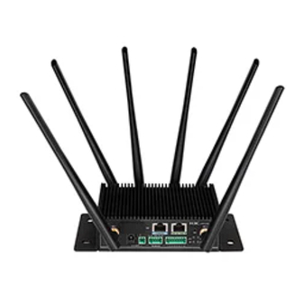
Installation accessories Table2-4 Installation accessories Accessory Diagram Obtaining method Remarks Mounting ears and The device comes with Provided screws mounting ears. Screw anchor and Provided screw DIN rail and screws Provided Six antennas. An antenna can be Antenna Provided installed to an NR antenna port or a Wi-Fi antenna port. -
Page 17: Installing The Device
Installing the device Mounting the device to a desktop Be careful to place the device upright on a clean, stable workbench. Figure3-1 Installing device to desktop Mounting the device to a wall CAUTION: • The installation accessories of different products might have different appearances. •... - Page 18 Pass the screws that match the screw anchors through the corresponding installation holes, adjust the position of the device, and use a screwdriver to tighten the screws clockwise to secure the device to the wall. Figure3-3 Securing the device to the wall Pass the screws that match the DIN bracket through the corresponding installation holes, adjust the position of the device, and use a screwdriver to tighten the screws clockwise to secure the DIN bracket to the device.
- Page 19 Figure3-4 Securing the DIN bracket to the device Press the metal spring at the lower end of the DIN bracket against the DIN rail, lift the device upwards forcefully, and snap the upper end of the device's DIN bracket into the rail.
-
Page 20: Grounding The Device
Figure3-5 Snapping the DIN bracket into the rail Grounding the device CAUTION: • Correctly connecting the grounding cable is crucial to lightning protection and EMI protection. • Connect the grounding cable to the grounding system in the equipment room, and make sure the engineering grounding device is operating safely. - Page 21 Figure3-6 Connecting the grounding cable to the grounding hole on the device chassis (1) (1) Grounding screw (2) Ring terminal (3) Grounding sign (4) Grounding hole (5) Grounding cable Figure3-7 Connecting the grounding cable to the grounding hole on the device chassis (2) (1) Grounding screw (2) Ring terminal (3) Grounding sign...
-
Page 22: Connecting Cables
Connecting cables Connecting power supplies WARNING! • Make sure the device is correctly grounded. • Provide a circuit breaker for each power input. When you connect a power cord, make sure the circuit breaker is switched off. • To prevent adapter damage because of insufficient power, use the power adapter that came with the device for power supply. -
Page 23: Connecting An Ethernet Cable
Figure4-2 Connecting the power adapter Connecting an Ethernet cable Connecting the cable to a GE terminal block port Insert the end with a terminal block port of the Ethernet cable into the GE terminal block port. After device power-on, identify whether the Ethernet port LED is in correct state. Figure4-3 Connecting the cable to a GE terminal block port Connecting the cable to a GE RJ45 port Insert the end with an RJ45 port of the Ethernet cable into the GE RJ45 port. -
Page 24: Connecting Industrial Serial Cables
Figure4-4 Connecting the cable to a GE RJ45 port Connecting industrial serial cables Insert the end with a terminal block port of the industrial serial cable into the RS485/RS232 terminal block port. Figure4-5 Connecting an industrial serial cable... -
Page 25: Installing Antennas
Installing antennas Installing Wi-Fi antennas Facing the front panel of the device, tighten the antenna clockwise onto the device's WiFi antenna port. Figure5-1 Installing the antenna to the Wi-Fi antenna port Push the antenna upwards to a right angle position to complete the antenna installation. -
Page 26: Installing Nr Antennas
Figure5-2 Antenna installation completed Installing NR antennas Facing the rear panel of the device, tighten the antenna clockwise onto the device's NR antenna port. Figure5-3 Installing the antenna to the NR antenna port Push the antenna upwards to a right angle position to complete the antenna installation. - Page 27 Figure5-4 Antenna installation completed...
-
Page 28: Installing The Sim Card
Installing the SIM card IMPORTANT: • The SIM card is not provided by default; users can purchase one based on their actual needs. • The device offers two SIM card slots, supporting automatic switching between SIM cards. • When installing or removing a SIM card, please ensure the device is powered off to guarantee its normal operation. -
Page 29: Verifying The Installation
Verifying the installation During the installation, check the following items before each power-on each: • There is enough space around the device for heat dissipation. • The grounding cable is connected correctly. • The power source is as required by the device. •... -
Page 30: Device Initial Power On And Startup
• By default, the device operates in fit mode. • You can switch the operating mode of the CPE5100 between fit and cloud as needed. For more information about the fit mode, cloud mode, and operating mode switchover, see H3C CPE5100 Series 5G Wireless Data Terminal AP Operating Mode Switchover Operation Guide. -
Page 31: Logging In To The Device Through The Console Port
Logging in to the device through the CONSOLE port After the device is powered on, the PC terminal screen displays the following information: System is starting... Booting Normal Extend BootWare. …… System application is starting... Startup configuration file does not exist. User interface con0 is available. -
Page 32: Logging In To The Device Through The Web Interface
Enable Wi-Fi on the wireless client. Search for and connect to the Wi-Fi named H3C_XXXXXX, where XXXXXX is the last six digits of the device's MAC address. Execute the telnet wlan.h3c.com command on the CLI of the wireless terminal. Enter the default username and password, and change the password as needed upon prompt. -
Page 33: Logging In To The Web Interface Wirelessly
Enable Wi-Fi on the wireless client. Search for and connect to the Wi-Fi named H3C_XXXXXX, where XXXXXX is the last six digits of the device's MAC address. On the wireless endpoint, enter http://wlan.h3c.com in the address bar of a browser, and then press Enter to open the device login page. - Page 34 After you connect the device to the public network, log in to Cloudnet, add the device to the device list at a specific site on Cloudnet, and then view and manage the device remotely. For more information about logging in to Cloudnet, adding sites, and adding devices, see H3C Cloudnet Deployment Guide.
Need help?
Do you have a question about the CPE5100 and is the answer not in the manual?
Questions and answers