Advertisement
Advertisement
Table of Contents

Related Manuals for DKN technology SMART SEATED LEG PRESS


Summary of Contents for DKN technology SMART SEATED LEG PRESS
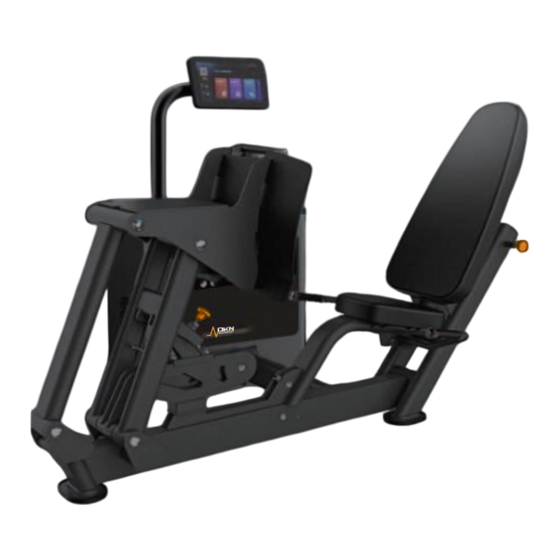
- Page 1 SMART SEATED LEG PRESS 20815 OWNER’S MANUAL WEBSITE...
- Page 2 Introduction Installation Indication As shown in the diagram: 1. Stand base 2. Base communication terminal 3. Stand communication terminal 4. M8*10 internal hexagon socket button head screw 5. Display stand Step 1: First, insert the base communication terminal (2) into the stand communication terminal (3) as shown in the diagram.
- Page 3 As shown in the diagram: As shown in the diagram: 1: Cross recessed pan head screw M4*8 2: Display back cover 1: Cable 2: Connecting pipe 3: Cross recessed pan head screw M3*6 4: Stand communication terminal 3: M12 flat washer 4: M12 spring washer 5: Cross recessed pan head screw M4*16 6: Control communication terminal...
-
Page 4: Preparation Before Use
10.The power plug must be reliably grounded, and try to avoid using other electrical Operating Instructions appliances on the same power supply line. Please do not use a damaged or wet power cord or plug. The power cord is dedicated. If damaged, it must be replaced by the Preparation before use: manufacturer, service center or personnel with relevant professional qualifications to avoid injury. -
Page 5: Mode Description
Mode Description: LED Light Description : We provide four resistance modes for the product, namely Standard Mode, Eccentric Mode, Isokinetic Mode, and Elastic Mode. Please refer to the following instructions for State Remark Color specific modes: Gradient effect Powered on, resistance not activated Blue (dark to light, light to dark) Mode... -
Page 6: Installation Precautions
Installation Precautions Specification 1. When removing the packaging on the surface of the packaging equipment, be careful not to scratch the surface of the machine with a knife. There must be enough personnel Model 20815 when moving equipment to prevent equipment from colliding or personal injury caused by insufficient personnel. -
Page 7: Assembly Step
Assembly Step 1 Assembly Step 2 Step Description Specification Step Description Specification Resistance frame Front swing frame Hexagon socket head cap screws M12*30 Main swing frame Hexagon socket head cap screws M10*35 Pedal Stand Spring washers Shaft 2 φ25*249 Spring washers Circlips for shafts φ25 Φ20*Φ10.5*2... - Page 8 Assembly Step 3 Assembly Step 4 Step Description Specification Step Description Specification Main frame Cushion adjustment plate Left handle Bar Shaft3 φ25*176 Right handle Bar Limit Rubber Flat Washers Φ20*Φ10.5*2 Circlips for shafts φ25 Flat Washers Φ16*Φ8.4*1.6 Hexagon socket head cap screws M12*35 Spring washers Hexagon socket head cap screws...
- Page 9 Assembly Step 6 Assembly Step 5 As shown below: Step Description Specification 1: Steel rope Flat Washers φ16*φ8.4*1.6 2: Connecting pipe 3: M12 flat washer Spring washers 4: M12 spring washer M8*30 Hexagon socket head cap screws 5: Hexagon socket bolt M12*30 Step First, after powering on (do not operate the interface), pull out the steel rope No.
-
Page 10: Cable Routing Diagram
Maintenance Attentions Cable Routing Diagram Daily Maintenance: 1.Clean the seat pad,back pad and cushion with warm water and soft cloth Correct Mistake in order to avoid the sweat erosion to these component . 2.Clean the frame with warm water and soft cloth 3.Cleaning chrome plated parts:wipe them with alcohol moistened soft cloth Monthly Maintenance: 1.Check transmission cable .Check the tightness and abrasion of the cable...
Need help?
Do you have a question about the SMART SEATED LEG PRESS and is the answer not in the manual?
Questions and answers