Advertisement
Quick Links
Advertisement

Related Manuals for DKN technology SC PRO


Summary of Contents for DKN technology SC PRO
- Page 1 SC PRO OWNER’S MANUAL OWNER’S MANUAL WEBSITE MANUAL...
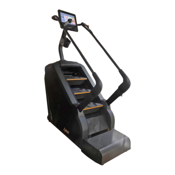
- Page 2 STAIR MACHINE...
- Page 3 WARNING Read all instructions carefully before using this product. Retain this owner’s manual for future reference: ----When using this treadmill, keep attaching the safety pull pin rope to your clothes. ----When you are running, keep your hand swinging natural, stare frontward, never look down at your feet.
- Page 4 13- Cut off the power when the equipment is not used. When the power is cut off , do not pull the power line to keep the wire unbroken. 14- Maximum weight of user: 180 KGS. 15- Pulse monitor data may not be accurate, can not be used for medicine. Over-exercise may cause injury, even death.
- Page 5 10. Always attach the safety pull pin rope to your clothing when using the treadmill. If the treadmill should suddenly increase in speed due to an electronics failure or the speed being inadvertently increased, the treadmill will come to a sudden stop when the pull pin is disengaged from the console.
- Page 6 WARNING! Consult your physician before starting with any exercise program. He can advise on the kind of training and which impact is suitable. WARNING! This machine is not suitable for therapeutic or medical purpose. WARNING! Over exercising may result in serious injury or death. If you experience dizziness, nausea, chest pain, or any other abnormal symptoms STOP EXERCISING IMMEDIATELY AND CONSULT A PHYSICIAN WITHOUT DELAY.
-
Page 7: Assembly Steps
ASSEMBLY STEPS STEP 1: 1. Open the package, take out all parts and place the main frame(1) on the flat ground. 2. Fasten the part A of pedal(40)(as P1 shows) to the part B of the main frame, please make sure the two parts are centred. - Page 8 STEP 2: 1. Connecting the Console extension wire (104) to the lower wire (105); 2. Assemble the support column(5) on the main frame(1) with screw(68), and washer(95); DO NOT TIGHTEN NOW. 3. Insert the decorative cover (58) and to the support column(5), then buckle it on the main frame(1).
- Page 9 STEP 3: 1: Pass the switch upper wire 1(106) through the right decorative cover (41R)to connect with the lower wire1 (107); 2: Insert the decorative cover (41L / R) on the support column (2L / R), assemble but not tighten the support column (2L / R) on the main frame(1) with screw(69) and washer(95), 3:Assemble but not tighten the handrail(3L/R) on the support column (2L / R) with screw(73) and washer(96)
- Page 10 STEP 4 1: Connect the pulse extension wire 1 (111) to the pulse extension wire 2 (112); connect the key board extension wire 1 (115) to the key board extension wire2 (116); 2: Insert the rear handrail(4) to the handrail (3L / R), then assemble but not tighten the rear handrail(4) to the handrail (3L / R) with screw(73) and washer(96);...
- Page 11 STEP 5: 1: As shown in Figure 1, connect the wires on the console (47) with the corresponding on the rear handrail (4) and the console support column (5); (matched by the same wire number) 2: Tighten the console (47) on the support column (5) with screw (78), then lock the decorative cover(48) on the console (47) with screw(82);...
-
Page 12: Console Manual
Console manual I: Start 1. Turn on the power switch, unscrew the two emergency stop switches, and ensure that there is no obstruction in the infrared induction area 2、 Press the armrest button or tap the screen stepper to start in the lowest gear. - Page 13 ◆ ◆ The controls of the main interface are explained in detail: : icon Function Description icon Function Description T T i i m m e e d d a a t t e e a a p p p p l l y y U U s s e e d d t t o o d d i i s s p p l l a a y y...
- Page 14 S S p p o o r r t t s s c c e e n n t t e e r r S S e e t t u u p p B B u u i i l l t t - - i i n n w w a a y y s s o o f f B B u u i i l l t t - - i i n n b b a a s s i i c c s s e e t t t t i i n n g g s s...
- Page 15 parameters: 2. Application Built-in third-party music and video APP applications ◆ The five functional modules of the Internet all need to be connected to the WIFI network to be used; ◆ Support playback of MP3, MP4, MOV, APE, and other common audio and video format files; ◆...
- Page 16 tapicon, Enter the application interface: ◆ Introduction motion interface third-party apps...
- Page 17 Control catalog S S t t a a r r t t b b u u t t t t o o n n : : C C l l i i c c k k t t o o s s t t a a r r t t t t h h e e s s t t e e p p p p e e r r B B a a c c k k k k e e y y : : C C l l i i c c k k t t o o r r e e t t u u r r n n t t o o t t h h e e p p r r e e v v i i o o u u s s l l a a y y e e r r M M a a i i n n i i n n t t e e r r f f a a c c e e k k e e y y : :...
- Page 18 3、Get started quickly tapicon,Start the 3, 2, 1 countdown to enter the motion interface: Exercise Step Calorie Time out Stop Heart rate Cadence time counting Accelera tion and decelera Fast speed gear adjustment height tion gears...
- Page 19 Program motion 4、 Click icon,Go to the program motion interface (36 fixed programs built-in): Set up any P1-P36 program, choose your exercise time and click Start. 5. Sports center Built-in 6 exercise modes: time countdown, calorie countdown, height countdown, step countdown, floor mode, custom. ◆...
- Page 20 ◆ Please pay attention to your heart rate value at any time during exercise, the maximum heart rate value is controlled at 220 minus age (this is the limit value, general exercise does not exceed 90% of this value as well) every minute, if it is an older athlete, this number needs to be lowered;...
- Page 21 ◆The user selects the movement time according to the needs, the built-in fixed time, the finger drags the circle button on the window or slides up and down the time value to set the movement time, once the setting is OK, click button, the movement begins;...
- Page 22 Click Floor Mode icon, enter the Floor Mode Page: Click Start to start floor mode Click Customize the icon to enter the customization settings - 4 -...
- Page 23 page: 控件目录 P P r r o o g g r r a a m m l l i i s s t t : : B B u u i i l l t t - - i i n n U U 1 1 - - U U 1 1 6 6 A A t t o o t t a a l l o o f f 1 1 6 6 p p r r o o g g r r a a m m d d a a t t a a c c a a n n b b e e s s e e l l e e c c t t e e d d b b y y u u s s e e r r s s ;...
- Page 24 Press the stop button, the ladder machine smoothly slow down to stop running, the system will automatically calculate the results of this exercise, pop up the relevant report card interface. 6、Set up Built-in basic settings (brightness adjustment, volume adjustment, language selection, machine management, factory mode, one-click cleaning) and WIFI settings two major functions;...
- Page 25 ◆ ◆ T T h h e e s s y y s s t t e e m m w w i i l l l l p p r r o o h h i i b b i i t t u u s s e e r r s s f f r r o o m m i i n n s s t t a a l l l l i i n n g g o o t t h h e e r r A A P P P P a a p p p p l l i i c c a a t t i i o o n n s s t t o o a a v v o o i i d d c c r r a a s s h h i i n n g g t t h h e e s s t t e e p p p p e e r r s s y y s s t t e e m m ;...
- Page 26 6. Precautions ◎ In order to ensure the normal use of the equipment, please do not download the device; ◎ Please regularly clean the cache of the device; ◎ WIFI Restrictions: This product cannot link to WIFI that requires WIFI web page verification. ◎...
-
Page 27: Grounding Methods
GROUNDING METHODS This product must be grounded. If it should malfunction or breakdown, grounding provides a path of least resistance for electric current to reduce the risk of electric shock. This product is equipped with a cord having an equipment-grounding conductor and a grounding plug. -
Page 28: Warranty
WARRANTY DKN-Technology warrants this product to be free from defects in material at the time of the product’s tender of delivery. This ‘Carry-in’ Limited Warranty applies for a period of two (2) years, beginning on the date mentioned on your product invoice or proof of purchase of product issue by DKN-Technology. -
Page 29: Exploded Drawing
EXPLODED DRAWING - 11 -... - Page 30 - 12 -...
-
Page 31: Parts List
PARTS LIST Part Part Description Description Anti slip pad Main frame EVA silencing pad 2L/R Support columns 1 p.r. Roller 3L/R Handrails 1p.r. Allen bolt M10 * 40 Rear handrail Allen bolt M10 * 170 Console support column Outer hexagon bolt M10 * 45 Rear pedal Allen bolt M10 * 30 Front roller... - Page 32 Upper protective cover 2 Flat washer Φ 8 Flat washer Φ 6 Rear cover Controller Pedal Decorative cover Power cord 41L/R 1p.r Console upper wire 42L/R Upper cover 1p.r Console extension wire 43L/R Lower cover 1p.r 44L/R Exterior decorative cover 1p.r Console lower wire 45L/R...
- Page 33 WEBSITE Make an Appointment to Visit our Showroom...
Need help?
Do you have a question about the SC PRO and is the answer not in the manual?
Questions and answers