Advertisement
Advertisement
Table of Contents

Related Manuals for DKN technology SMART LEG EXTENSION/LEG CURL


Summary of Contents for DKN technology SMART LEG EXTENSION/LEG CURL
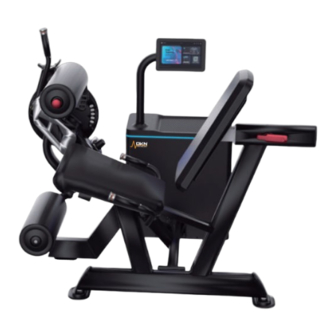
- Page 1 SMART LEG EXTENSION / LEG CURL 20817 OWNER’S MANUAL WEBSITE...
- Page 2 Introduction Installation Indication As shown in the diagram: 1. Stand base 2. Base communication terminal 3. Stand communication terminal 4. M8*10 internal hexagon socket button head screw 5. Display stand Step 1: First, insert the base communication terminal (2) into the stand communication terminal (3) as shown in the diagram.
-
Page 3: Safety Precautions
As shown in the diagram: As shown in the diagram: 1: Cable 1: Cross recessed pan head screw M4*8 2: Connecting pipe 2: Display back cover 3: M12 flat washer 3: Cross recessed pan head screw M3*6 4: M12 spring washer 4: Stand communication terminal Step 1: First, power on the device (do not operate the interface). -
Page 4: Preparation Before Use
9.Please make sure to read all instructions before use. The factory is not responsible for Operating Instructions any personal injury or property damage caused by improper use of this product. Preparation before use: 10.The power plug must be reliably grounded, and try to avoid using other electrical appliances on the same power supply line. -
Page 5: Mode Description
Mode Description: LED Light Description : We provide four resistance modes for the product, namely Standard Mode, Eccentric Mode, Isokinetic Mode, and Elastic Mode. Please refer to the following instructions for State Color Remark specific modes: Gradient effect Powered on, resistance not activated Blue (dark to light, light to dark) Mode... -
Page 6: Assembly Step
Assembly Step 1 7. Pay attention to the order of locking nuts when installing. Do not lock the nuts being installed until the entire equipment is installed. Only lock the nuts one by one after the Step Description Specification entire machine is installed. Door Frame 8. - Page 7 Assembly Step 3 Assembly Step 2 Step Description Specification Step Description Specification Leg press frame Main frame Kick stand Rotating frame Adjusting rod Cam frame Swing rack Shaft l φ25*112 Metallurgy set Shaft 2 φ38*φ25*180 φ60.5*15 Aluminum plate Aluminum plate Socket Flat head screw M8*25 Socket Flat head screw...
- Page 8 Assembly Step 4 Assembly Step 5 Step Description Specification Step Description Specification Flat washer Block ring φ20*φ10.5*2 Spring Left handle frame Pull up a knob M10*35 Right handle frame M20 nut Socket cap screw Aluminum plate Support frame Socket Flat head screw M8*25 Adjusting frame of back pad Leg pad...
- Page 9 Assembly Step 6 Maintenance Attentions Daily Maintenance: Step Description Specification Spring washer 1.Clean the seat pad,back pad and cushion with warm water and soft cloth in order to avoid the sweat erosion to these component . Flat washer 16*08.4*1.6 2.Clean the frame with warm water and soft cloth Socket cap screw M8*30 3.Cleaning chrome plated parts:wipe them with alcohol moistened soft cloth...
Need help?
Do you have a question about the SMART LEG EXTENSION/LEG CURL and is the answer not in the manual?
Questions and answers