
Related Manuals for Telex AIRMAN 8+


Summary of Contents for Telex AIRMAN 8+
- Page 1 AIRMAN 8+ AIRMAN8P‑0210 DOUBLE SIDE ANR HEADSET | AIRMAN8P‑0211 DOUBLE SIDE ANR HEADSET | AIRMAN8P‑0212 DOUBLE SIDE ANR+ HEADSET Customer Maintenance Manual...
-
Page 3: Table Of Contents
AIRMAN 8+ Table of contents | en Table of contents Record of revisions Purpose of manual Technical support Parts ordering Repairs Safety precautions Introduction Parts list and exploded view Exploded view Parts list Maintenance Recommended maintenance schedule Basic inspection 5.2.1 Physical inspection Microphone troubleshooting 5.3.1... -
Page 4: Record Of Revisions
en | Record of revisions AIRMAN 8+ Record of revisions Revision No. Revision Date Change Description 07/2020 Created 12/2020 Added Item 31, 32, 33 to the parts list. Minor typo fixes 01/2021 Added Headband Pad and Holder for Airman 8+ to the exploded view and parts table 04/2022 Updated to include P5P to... -
Page 5: Purpose Of Manual
When writing, include all information concerning problems and mail to: To find the proper address and phone number for your region, please reference https:// telex.com/aviation-solutions/about-telex-aviation-headsets/contact-telex-aviation/ Parts ordering Replacement parts may be ordered from our parts department. When ordering, please include the following information: –... - Page 6 en | Purpose of manual AIRMAN 8+ 2023-08 | 05 | F.01U.387.060 Bosch Security Systems, LLC Customer Maintenance Manual...
-
Page 7: Introduction
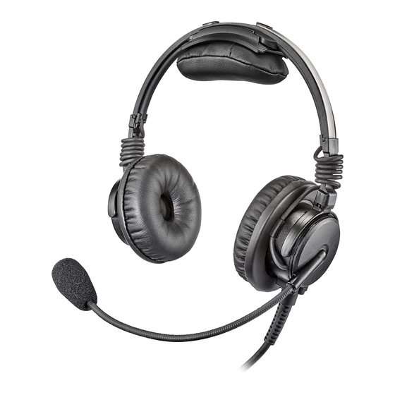
The Airman 8+ is among the lightest Active Noise Reduction headsets on the market and one of only three FAA TSO C139a approved ANR headsets to utilize Telex’s proprietary battery-free system. Soft pliable ear cushions and headband pads combine with dual direction ear cup pivots to provide long flight wearing comfort. - Page 8 en | Introduction AIRMAN 8+ Reference View Headband Pad Headband Pad Holder Headset Gliders Ear Cushions Boom Rotator Windscreen / Microphone Cord with Strain Relief Boom 2023-08 | 05 | F.01U.387.060 Bosch Security Systems, LLC Customer Maintenance Manual...
-
Page 9: Parts List And Exploded View
AIRMAN 8+ Parts list and exploded view | en Parts list and exploded view Exploded view 32, 33 30, 31 24 & 34 2, 3, 4 Parts list Item Part No. Description Model -0210 -0211 -0212 AIRMAN8P-0909 F.01U.382.338 CARRYING CASE AIRMAN7-0900 F.01U.313.415 WINDSCREEN (2PCS) - Page 10 en | Parts list and exploded view AIRMAN 8+ Item Part No. Description Model -0210 -0211 -0212 ESP-F01U360393 F.01U.383.827 AIRMAN8P-0910 F.01U.382.339 SANITARY COVER, AIRMAN 8+ (10PCS) ESP-F01U379003 F.01U.383.830 SPP SANITARY COVER, AIRMAN 8+ (2PCS) AIRMAN8P-0903 F.01U.382.337 EAR CUSHION, AIRMAN 8+ (2PCS) ESP-F01U347235 F.01U.383.825 SPP Ear cushion Airman 8+ (2pcs)
- Page 11 -0210 -0211 -0212 22 ESP-F01U380742 F.01U.383.833 PCBA, BOOM SIDE, AIRMAN 8+ ESP-F01U401631 F.01U.406.428 PCBA, BOOM SIDE, AIRMAN 8+ P5P 23 S-F01U342097 F.01U.342.097 LABEL, TELEX 24 ESP-F01U384604 F.01U.383.824 CORD UNIT, XLR, 5M ESP-F01U402172 F.01U.406.429 SPA CABLE ASSEMBLY, AIRMAN 8P P5P ESP-F01U379469 F.01U.389.975 SPEAKER ASSY,...
-
Page 12: Maintenance
en | Maintenance AIRMAN 8+ Maintenance The Airman 8+ headset is designed so that ANR performance and boom microphone sensitivity can be adjusted as required to meet specification requirements. These headset adjustments are made in order to alter performance. All other maintenance requires replacement of parts, fixing open wires, or removing shorted wires. -
Page 13: Basic Inspection
AIRMAN 8+ Maintenance | en Basic inspection Basic Inspection Physical Inspection Perform Talk Test Talk Test Passed, Did Talk Test Pass? Minimal check What didn´t pass? Mic not working Speaker not working ANR not working Speaker Speaker Speaker Speaker Perform Talk Test Reeinstall in Aircraft Passed Did it pass? -
Page 14: Microphone Troubleshooting
en | Maintenance AIRMAN 8+ Test When performing a talk test, things to be aware of: – Note any unusual or unexpected noises, static, and oscillations. – Note any distorted audio. – Turn ANR on and note noise reduction of fans, ambient noise etc. –... -
Page 15: Validate Mic Circuitry
AIRMAN 8+ Maintenance | en 5.3.2 Validate mic circuitry To validate the mic PCBA, do the following: Construct a test circuit. Connect the test circuit to the microphone plug of the headset. For more information, see Connectors. Test for an audio signal. If audio signal is detected, the board is valid. -
Page 16: Speaker Troubleshooting
en | Maintenance AIRMAN 8+ Speaker troubleshooting 5.4.1 Speaker sensitivity and frequency response verification Notice! This headset was designed, tested, and approved to FAA TSO C139a. The TSO requires the headset meet the minimum performance specifications as defined in RTCA DO-214a. This document and specifications listed here reference the test procedures and equipment used as defined in these standards. -
Page 17: Measure The Resistance (Plug To Pcba)
AIRMAN 8+ Maintenance | en 5.4.2 Measure the resistance (plug to PCBA) To measure the resistance, do the following: Using an ohmmeter, place one probe on J5. Place the other probe on J6 or J17. If measured at 300Ω ±20%, continuity is good. If measured at 600Ω, one of the speaker paths is defective. - Page 18 en | Maintenance AIRMAN 8+ Troublehoot Speaker Does audio pass Does ANR pass Final Talk Test Troubleshoot Mic with no power? the Talk Test? Turn the power and ANR on Does ANR work? Adjust the ANR No ANR on the headset Adjust the ANR Does ANR work? Measure Voltage on...
-
Page 19: Measuring Anr Circuit Voltages And Switch Function
AIRMAN 8+ Maintenance | en 5.5.1 Measuring ANR circuit voltages and switch function Notice! This headset was designed, tested, and approved to FAA TSO C139a. The TSO requires the headset meet the minimum performance specifications as defined in RTCA DO-214a. This document and specifications listed here reference the test procedures and equipment used as defined in these standards. -
Page 20: Cleaning The Headset And Connectors
en | Maintenance AIRMAN 8+ Cleaning the headset and connectors Caution! Do not allow alcohol or any liquid to touch the speaker or microphone element directly. To clean the headset, do the following: Using a mild detergent with water and a soft towel, or isopropyl alcohol wipes, clean the plastic and metal headset parts. -
Page 21: Replacing The Windscreen
AIRMAN 8+ Maintenance | en 5.10 Replacing the windscreen The foam windscreen can be cleaned using low-pressure air to blow contaminates off the exterior. If low-pressure air does not provide effective results, the windscreen should be replaced. Caution! Do not use any liquid on the foam windscreen. To remove the windscreen, do the following: Grasp the microphone windscreen and gently pull away from the microphone. -
Page 22: Disassembly
en | Disassembly AIRMAN 8+ Disassembly The following procedure describes the complete disassembly of the Airman 8+ headset. Notice! The removal process requires the following steps to be followed in the order described. Assembly is the reversal of the disassembly procedure. Please take car when disassembling to note details that may be required in the reassembly process, such as the locations of disconnected wires. -
Page 23: Headband Pad And Headband Pad Replacement
AIRMAN 8+ Disassembly | en Headband pad and headband pad replacement To replace the headband pads, do the following: At one end of the headband pad holder, carefully slide the holder from the headband cover. With the new headband pad holder, slide the headband pad holder over the headband cover. - Page 24 en | Disassembly AIRMAN 8+ To replace the headband pad, do the following: Grasp the edge of the headband pad. Gently pull the headband pad away from the headpad holder. Align the new headband pad with the Velcro on headpad holder. 2023-08 | 05 | F.01U.387.060 Bosch Security Systems, LLC Customer Maintenance Manual...
- Page 25 AIRMAN 8+ Disassembly | en Firmly press the new headband pad into place. Bosch Security Systems, LLC 2023-08 | 05 | F.01U.387.060 Customer Maintenance Manual...
-
Page 26: Remove The Mic Prefilter
en | Disassembly AIRMAN 8+ Remove the mic prefilter To remove the prefilter, do the following: Carefully pry the prefilter from the mic. Remove the yoke assembly from the headband assembly To remove the yoke assembly from the headband assembly, do the following: Use a fingernail to lift the bottom edge of the black plastic spacer. - Page 27 AIRMAN 8+ Disassembly | en Using a T-5 screwdriver, remove three screws (as shown). Remove the house and the yoke/glider assembly. Using a T-5 screwdriver, remove two screws (as shown). Remove the PCBA. Using a soldering iron, carefully disconnect the wires from the speaker, overhead cord, boom mic assembly, and ANR mic solder terminals, as needed.
-
Page 28: Non-Boom Side Disassembly
en | Disassembly AIRMAN 8+ Notice! Take care to avoid touching the plastic housing with the soldering iron. Non-boom side disassembly To remove the speaker assembly and sleeve, do the following: Pushing the two retaining cams simultaneously on the speaker assembly, rotate the speaker faceplate approximately 15°... - Page 29 AIRMAN 8+ Disassembly | en Remove the house and the yoke/glider assembly. Using a T-5 screwdriver, remove two screws (as shown). Remove the PCBA. Using a soldering iron, carefully disconnect the wires from the speaker and overhead cord, and ANR mic solder terminals, as needed. Bosch Security Systems, LLC 2023-08 | 05 | F.01U.387.060 Customer Maintenance Manual...
-
Page 30: Assembly
en | Assembly AIRMAN 8+ Assembly Boom side assembly To assemble the boom side assembly, do the following: Solder the overhead cord to the PCBA. Blue White Shield Black Solder the cable assembly to the PCBA. Thread the boom mic wires through the center hole. Using the two shorter screws, attach the PCBA to the boom mic assembly. - Page 31 AIRMAN 8+ Assembly | en Solder the main cord to the PCBA Airman8P-0210 Airman8P-0211 Airman8P-0212 Yellow No connection Black Drain wire + blue White No Conn. Route the speaker wires through the housing and solder to the PCBA. White Route the overhead cord and the headset cord through the corresponding grooves provided on the boom.
- Page 32 en | Assembly AIRMAN 8+ Notice! The side with the deep grooves goes toward the speaker. 11. Place the housing on the boom mic assembly. 12. Make sure the overhead cord is in the correct slot and the jacket is fully inside the housing.
-
Page 33: Non-Boom Side Assembly
AIRMAN 8+ Assembly | en 16. Carefully wind the overhead cord around the glider. Non-boom side assembly To assemble the non-boom side assembly, do the following: Solder the overhead cord to the PCBA. Blue White Shield Black Using the two shorter screws, attach the PCBA to the cover. 1 Alignment posts for PCBA screw 2 Path for overhead cord Solder the wires to the speaker. - Page 34 en | Assembly AIRMAN 8+ White Route the speaker wires through the housing and solder to the PCBA. Place yoke on the housing. Notice! Take care to verify the orientation of the yoke, because it does not rotate 360°. Place the cover on the housing. Using a T-5 screwdriver, replace the three screws (as shown) to attach the yoke and housing to the PCBA.
- Page 35 AIRMAN 8+ Assembly | en Position the overhead cord in the retaining clip and align the knob of the faceplate toward the bottom. Align the four tabs on the faceplate, and then rotate counterclockwise to lock. Notice! Verify all four tabs engage and retaining tabs are in the groove. 10.
-
Page 36: Attach The Prefilter
en | Assembly AIRMAN 8+ Attach the prefilter To attach the prefilter, do the following Carefully clip the prefilter to the mic. Replace the yoke assembly on the headband assembly To replace the yoke assembly on the headband assembly, do the following: Slide the yoke assembly onto the headband. -
Page 37: Reinstall The Headband Cover
AIRMAN 8+ Assembly | en Reinstall the headband cover To reinstall the headband cover, do the following: Take care to verify the overhead cord lays between the guides. Ensure the cover fully encloses around the headband at both sides. Bosch Security Systems, LLC 2023-08 | 05 | F.01U.387.060 Customer Maintenance Manual... -
Page 38: Wiring Diagrams And Connectors
en | Wiring Diagrams and Connectors AIRMAN 8+ Wiring Diagrams and Connectors Airman 8+ Series headsets are available with multiple connector styles depending on the application of use. All models utilize custom cables developed specifically for in cockpit use. All connection points implement strain and bend relief features to provide long-term durability. - Page 39 AIRMAN 8+ Wiring Diagrams and Connectors | en Pin Description Color Mic Power and White Signal (ANR Power +) Mic Power and Blue/Inner Shield Signal (ANR Power -) ANR Power Table 8.3: Airman8P-0212 Notice! The Airman 8+ automatically uses power from pin 5, if it is provided by the aircraft. The Airman8P-0212 MUST have power on pin 5 for ANR to function.
- Page 40 en | Wiring Diagrams and Connectors AIRMAN 8+ Figure 8.4: Airman 8P-0211 Wiring Diagram Figure 8.5: Airman8P-0212 Wiring Diagram 2023-08 | 05 | F.01U.387.060 Bosch Security Systems, LLC Customer Maintenance Manual...
- Page 41 AIRMAN 8+ Wiring Diagrams and Connectors | Bosch Security Systems, LLC 2023-08 | 05 | F.01U.387.060 Customer Maintenance Manual...
- Page 42 | Wiring Diagrams and Connectors AIRMAN 8+ 2023-08 | 05 | F.01U.387.060 Bosch Security Systems, LLC Customer Maintenance Manual...
- Page 44 202307312140...
Need help?
Do you have a question about the AIRMAN 8+ and is the answer not in the manual?
Questions and answers