Telex Airman 850 Maintenance And Overhaul Manual
Hide thumbs
Also See for Airman 850:
- Brochure & specs (20 pages) ,
- Operating instructions manual (13 pages) ,
- Customer maintenance manual (34 pages)

Related Manuals for Telex Airman 850


Summary of Contents for Telex Airman 850
- Page 1 Airman 850 Headset Maintenance and Overhaul Manual for the Airman 850 Headset Rev. 05 JUNE/2018 F.01U.264.819...
- Page 2 Airman 850 Record of Revisions Rev No. Revision Date Change Description 03/2004 Created 02/2012 This document was completely reformatted and version letter was changed to a version number 05/2012 Page 24 11/2017 Never released 06/2018 Updated entire document and validated content...
- Page 3 Airman 850 Purpose of Manual This manual, Bosch part number F.01U.264.819, contains information for the overhaul and servicing of the Airman 850 headset. Technical Support A liaison between the customer and factory is provided by the Bosch Product Support Department. Consultation and assistance on technical problems, part information, and availability of local and factory repair facilities is available.
- Page 4 Airman 850...
-
Page 5: Table Of Contents
4.1 Airman 850 Wiring Diagram (Catalog Numbers 301317-000, -002, -003, -101, and -400) ....................... 21 4.2 Airman 850 Wiring Diagram (Catalog Numbers 301317-200, -201, and -300)....23 4.3 Connector Views/Wiring Diagrams ................. 24 4.3.1 Connector View for Catalog Numbers 301317-000, -003, -200, ... - Page 6 Airman 850 4.3.2 Connector View for Catalog Numbers 301317-101 and -201 ......... 24 4.3.3 Connector View for Catalog Numbers 301317-002 ..........24 4.3.4 Connector Wiring Diagram for Catalog Numbers 301317-000, -003, -101, -200, -201, -300, and -400 ..................25 4.3.5 Connector Wiring Diagram for Catalog Number 301317-002 (5-Pin XLR)... 25 ...
-
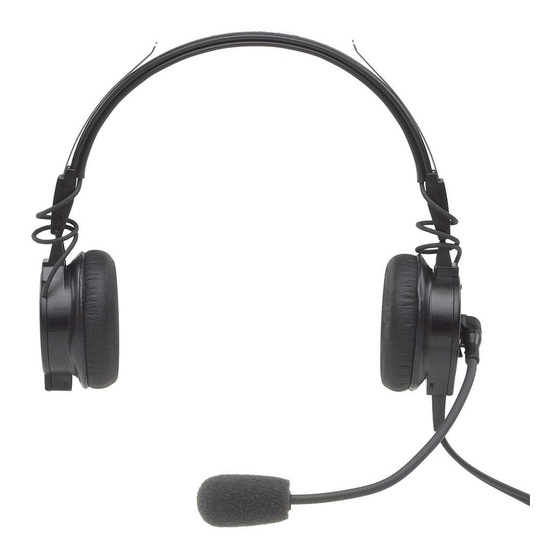
Page 7: Description And Specifications
Lightweight design with soft, pliable cushions, adjustable headband, extended frequency drivers, and a noise canceling electret microphone result in a comfortable headset providing the ultimate in clear, understandable communications. The Airman 850 headset with boom microphone is approved for aircraft use under FAA TSO’s C57a and C58a. 1.2 Models Covered This manual only covers models listed here. -
Page 8: Specifications
8 Description and Specifications Airman 850 1.3 Specifications Receivers: Type: Dynamic Impedance: See Table 2 on page 9. CAUTION: Damage could occur to avionics equipment if used with headset versions which are not manufactured for use with 600 Ohm headsets. If in doubt, consult the avionics equipment manufacturer. - Page 9 150 Ohms 301317-002 Airman 850 Headset, Dual-sided 600 Ohms 301317-003 Airman 850 Headset, Dual-sided 600 Ohms 301317-101 Airman 850 Headset, Dual-sided, customer specific 150 Ohms 301317-200 Airman 850 Headset, Single-sided 150 Ohms 301317-201 Airman 850 Headset, Single-sided, customer specific 150 Ohms...
- Page 10 10 Description and Specifications Airman 850...
-
Page 11: Disassembly/Assembly
Disassembly/Assembly 2.0 Disassembly/Assembly 2.1 Disassembly The following procedure allows for complete disassembly of the Airman 850 final assembly (see Figure 1 and Figure 2). IMPORTANT: The removal process requires the steps to be followed in order. For example, to remove the boom assembly, item 13, all steps before the Removing the Boom Assembly step must be completed and in the listed order. -
Page 12: Remove Sleeve (Item 8)
12 Disassembly/Assembly Airman 850 2.1.3 Remove Sleeve (Item 8) To remove the sleeve, do the following: Carefully slide a small tweezers or pick under the sleeve. Avoid touching or scratching the circuit board, item 9 or 10. NOTE: Gently pry the sleeve up and away from the circuit board. -
Page 13: Assembly
Please take care to properly align parts and wires to ensure proper operation. See disassembly procedure, parts lists, assembly diagrams, and wiring diagrams for reference. Airman 850 Headset, Dual Sided, Exploded View FIGURE 1. - Page 14 14 Disassembly/Assembly Airman 850 Airman 850 Headset, Single Sided, Exploded View FIGURE 2.
- Page 15 Airman 850 Disassembly/Assembly 15 Catch 10° (Push from other side of faceplate Catch (Push from other Assemble side of faceplate Remove Faceplate Disassembly/Assembly View FIGURE 3.
- Page 16 16 Disassembly/Assembly Airman 850...
-
Page 17: Chapter 3 Parts List
CHAPTER 3 Parts List 3.0 Parts List 3.1 General When replacing parts, consult Figure 1 on page 13, Figure 2 on page 14, and the parts list. Choose the parts corresponding to the catalog/model number on the Headband Assembly (Figure 1 on page 13, item 1). -
Page 18: Airman 850, Catalog Number 301317-000, -002, -003, -101, -200, -201, -300, And -400
18 Parts List Airman 850 Customer Maintenance Manual 3.2 Airman 850, Catalog Number 301317-000, -002, -003, -101, -200, -201, -300, and -400 MODEL Item CTN Numbers SAP Numbers Description 000 002 003 101 200 201 300 400 64318095 F01U152147 HEADBAND ASSEMBLY... - Page 19 Airman 850 Customer Maintenance Manual Parts List 19 MODEL Item CTN Numbers SAP Numbers Description 000 002 003 101 200 201 300 400 701610000 F01U152470 COVER,NON-BOOM SIDE 800789000 F01U153679 BOOM ASSEMBLY 800789100 F01U153680 BOOM ASSEMBLY 74169A F01U153213 WINDSCREEN 800456019 F01U110451...
- Page 20 20 Parts List Airman 850 Customer Maintenance Manual...
-
Page 21: Chapter 4 Wiring Diagrams
CHAPTER 4 Wiring Diagrams 4.0 Wiring Diagrams 4.1 Airman 850 Wiring Diagram (Catalog Numbers 301317-000, -002, -003, -101, and -400) Top Side, Airman 850 Headset, Dual-Sided Wiring Diagram FIGURE 4. - Page 22 22 Wiring Diagrams Airman 850 Bottom side, Airman 850 Headset, Dual-Sided Wiring Diagram FIGURE 5.
-
Page 23: Airman 850 Wiring Diagram (Catalog Numbers 301317-200, -201, And -300)
Airman 850 Wiring Diagrams 23 4.2 Airman 850 Wiring Diagram (Catalog Numbers 301317-200, -201, and -300) Airman 850 Headset, Single-Sided Wiring Diagram FIGURE 6. -
Page 24: Connector Views/Wiring Diagrams
Airman 850 Headset, Connector View (Molded Plugs) FIGURE 7. 4.3.2 Connector View for Catalog Numbers 301317-101 and -201 Airman 850 Headset, Connector View (Mechanical Plugs) FIGURE 8. 4.3.3 Connector View for Catalog Numbers 301317-002 Airman 850 Headset, Connector View ( XLR Plug) FIGURE 9. -
Page 25: Connector Wiring Diagram For Catalog Numbers 301317-000, -003, -101, -200, -201, -300, And -400
Airman 850 Headset, Connector Wiring Diagram FIGURE 10. 4.3.5 Connector Wiring Diagram for Catalog Number 301317-002 (5-Pin XLR) Pin 5 N/C Pin 1 White Pin 4 Black (shield) Pin 2 Yellow Pin 3 Red Airman 850 Headset, 5-pin XLR Wiring Diagram FIGURE 11. - Page 26 26 Wiring Diagrams Airman 850...
-
Page 27: Chapter 5 Maintenance
2. Connect the test circuit to the microphone plug of the headset. For more information, see “Connector Views/Wiring Diagrams” on page 24. Verify correct polarity of connections. NOTE: Airman 850 Headset Boom Microphone Sensitivity Check and Adjustment Test Circuit FIGURE 12. -
Page 28: Microphone Sensitivity Adjustment
To adjust microphone sensitivity, do the following: >Turn the gain adjustment control in the microphone housing, using a small screwdriver. For more information, see Figure 13. >Clockwise adjustment increases output level. Gain Adjustment Airman 850 Headset, Boom Microphone Gain Adjustment Location FIGURE 13. -
Page 29: Troubleshooting Mic Failure
• If no output, or no acceptable output is obtainable, then replace the boom assembly. 1/2W 25uf 25uf 25 Vdc 12 Vdc DEVICE UNDER TEST V IN V OUT Airman 850 Headset, Boom Assembly Test Circuit FIGURE 14. - Page 30 30 Maintenance Airman 850 GREEN COPPER Airman 850 Headset, Boom Assembly Reference View FIGURE 15. 5.1.3.2 Testing the Circuit Board Assembly This test is for testing the circuit board assembly 600704-100 only. No testing is IMPORTANT: required for circuit board 800940-000.
-
Page 31: Speaker Validation And Adjustment
Airman 850 Maintenance 31 5.2 Speaker Validation and Adjustment 5.2.1 Speaker Sensitivity and Frequency Response Verification Headphone specifications are designed to comply with FAA TSO C57a, NOTE: DO-214 & DO-160D. The headphone has two (2) operations (ANR version only): ... -
Page 32: Anr Validation And Adjustment
+0.000 5.3.3 ANR Test Procedure 5.3.3.1 Required Equipment The Airman 850 ANR test and adjustment procedure requires the following acoustic test equipment and custom fixture. 1. Audio Test System (for purposes of this procedure the Audio Precision System 2 is referenced) 2. - Page 33 Airman 850 Maintenance 33 Test Setup Block Diagram 5.3.3.2 Test Setup Block Diagram FIGURE 17. Custom ANR Fixture 5.3.3.3 Custom ANR Test Fixture with Headset FIGURE 18. 5.3.3.4 Testing ANR To test ANR, do the following: 1. Create a standard microphone test setup.
-
Page 34: Cleaning The Unit
34 Maintenance Airman 850 With ANR turned on, perform a bandpass sweep, save this file. • 5. Subtract the two sweep results (files), measured in step 3. The resulting curve should fit within the limits as shown in “Minimum Attenuation Requirements (Linearize between points)” on page 32. -
Page 35: Chapter 6 Troubleshooting
CHAPTER 6 Troubleshooting 6.0 Troubleshooting Chart Check Check Check Check Check Check Check Plugs Main Cord Amplifier Overhead Speakers Boom Mic Circuit Gain Assembly Boards Cord Adjust Receiver Inoperative Microphone Inoperative Receiver Intermittent Microphone Intermittent Distorted Receiver Signal Distorted Microphone Signal Receiver Level... - Page 36 36 Troubleshooting Airman 850...
- Page 37 APPENDIX A ANR Fixture...
- Page 38 Airman 850...
- Page 39 YYYYMMDD Drawn Checked Release Resp. dept. Size Treatment Missed Details Material From Lang. Weight Sheet AIRMAN 850 ANR TEST FIXTURE 1 / 1 Crit. P. Scale Doc.Type DP/TD Vers. Format F01UXXXXXX Mat. meets Syst. Repl. for Repl. by ANR Test Fixture Drawing...
Need help?
Do you have a question about the Airman 850 and is the answer not in the manual?
Questions and answers