Telex AIRMAN 750 Customer Maintenance Manual
Hide thumbs
Also See for AIRMAN 750:
- Brochure & specs (20 pages) ,
- Maintenance & overhaul manual (34 pages)
Table of Contents
Advertisement
Quick Links
Advertisement
Table of Contents

Related Manuals for Telex AIRMAN 750


Summary of Contents for Telex AIRMAN 750
- Page 1 AIRMAN 750 Customer Maintenance Manual...
-
Page 3: Table Of Contents
General description Models covered Specifications Parts list General Airman 760, catalog number 64400-200 Airman 750, catalog number 64300-200, -205, -208, -210, -212,-218, -219, -220, and -300 Disassembly and assembly Disassembly 4.1.1 Removal of the receiver assembly 4.1.2 Removal of the cord assembly 4.1.3... - Page 4 | Table of contents AIRMAN 750 Troubleshooting Troubleshooting chart 2023-08 | 15 | F.01U.311.532 Bosch Security Systems, LLC Customer Maintenance Manual...
-
Page 5: General Information
Removed the Lincoln Nebraska address from the manual Purpose of manual This manual, Bosch part number F.01U.311.532, contains information for the overhaul and servicing of the Airman 750/760 headset. Technical support A liaison between the customer and factory is provided by the Bosch Product Support Department. -
Page 6: Parts Ordering
| General information AIRMAN 750 Parts ordering Replacement parts may be ordered from our parts department. When ordering, please include the following information: – Model Number – Part Description – Part Number – Quantity Mail to: Bosch Communications, LLC... -
Page 7: Description And Specifications
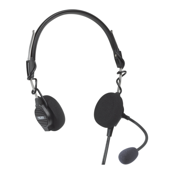
Description and specifications General description The Telex Airman 750 Headset and the Airman 760 Headphone are designed and engineered for high-quality aircraft communications. The Airman 750 is approved for aircraft use under the Federal Aviation Agency TSO C57a and C58a. The Airman 760 is approved for aircraft use under the Federal Aviation Agency TSO C57a. -
Page 8: Specifications
Within ±6 dB relative to the output at 1kHz between 350 Hz to 3000 Hz Sensitivity: 90 dB SPL ±5 dB at 1 kHz, 1 mW input (when tested with 6cc coupler) Microphone (Airman 750 only) Type: Noise-canceling amplified electret Matching impedance: 50 to 600 Ω... - Page 9 AIRMAN 750 Description and specifications | en Airman 750 Airman 760 Double-sided 4.8 oz. (136 g) Approximate wearing weight Airman 750 Airman 760 Single-sided 2.3 oz. (65 g) 2.2 oz. (62 g) Double-sided 3.2 oz. (91 g) Plug type Varies by model. Refer to Models covered, page 7 .
-
Page 10: Parts List
General When replacing parts, consult the illustration, Airman 760, catalog number 64400-200, page 10 and Airman 750, catalog number 64300-200, -205, -208, -210, -212,-218, -219, -220, and -300, page 11 . Choose the parts corresponding to the catalog/model. Figure 3.1: Airman 750/760 series-200/300 exploded view... -
Page 11: Airman 750, Catalog Number 64300-200, -205, -208, -210, -212,-218, -219, -220, And -300
GLIDER SPRING S-F01U327240 GLIDER SPRING (10-pack) Not Available as a CIRCUIT BOARD replaceable part S-64404024 HOUSING REAR, LEFT SIDE Airman 750, catalog number 64300-200, -205, -208, -210, -212,-218, -219, -220, and -300 Ordering Part Description Models Number 200 205 590404360... - Page 12 | Parts list AIRMAN 750 Ordering Part Description Models Number 63988025 CORD Approximate Length: 7 ft. (2.13 63988031 CORD Approximate Length: 6 ft. (1.82 70413002 CORD Approximate Length: 5.5 ft. (1.67 63988043 CORD Approximate Length: 8 ft. (2.4 m)
- Page 13 AIRMAN 750 Parts list | en Ordering Part Description Models Number 64308117 HOUSING (Receiver) ASSY PACKAGED, left side 64308110 HOUSING (Receiver) ASSY PACKAGED, right side 10 64404018 HOUSING REAR, right side ESP-F01U323856 HOUSING REAR, right side (printed) 11 64318069 HEADBAND...
- Page 14 | Parts list AIRMAN 750 Ordering Part Description Models Number S-F01U327240 GLIDER SPRING 10- piece 14 ESP-F01U402346 PCBA 15 64307008 BOOM ASSEMBLY 64307013 BOOM ASSEMBLY 16 59688000 WINDSCREE 800456001 WINDSCREE N + O-RING 580001003 OPTIONAL O-RING 18 70531004 TEMPLE...
-
Page 15: Disassembly And Assembly
AIRMAN 750 Disassembly and assembly | en Disassembly and assembly The following procedure allows for complete disassembly of the Airman 750 and Airman 760. Refer to the illustration and to Parts list, page 10 . Figure 4.1: Airman 750/760 series-200/300 exploded view Notice! Assembly is the reversal of the disassembly procedure. -
Page 16: Removal Of The Cord Assembly
Using a soldering iron, carefully disconnect the overhead cord wires from the receiver assembly. Figure 4.2: Circuit board / Receiver / Cord Wiring Notice! Airman 750 model -300 does not have overhead cord wires. 4.1.2 Removal of the cord assembly To remove the cord assembly, do the following: Gently remove the foam ear cushion (2) (and ear cushion pad if present). -
Page 17: Removal Of A Glider
Follow steps 1 to 2 in the procedure for removing the cord assembly. Refer to Removal of the cord assembly, page 16 . If disassembling an Airman 750, use a soldering iron on the circuit board to carefully disconnect the two boom wires from J10 and J11. -
Page 18: Wiring And Connectors
On the speaker, the positive terminal is usually indicated with a dot. 5.1.1 Catalog numbers 64300 -200, -220, -300 Notice! With model -300 omit overhead cordage. Figure 5.1: Airman 750 Headset Model -200, -220, -300 Wiring Diagram 2023-08 | 15 | F.01U.311.532 Bosch Security Systems, LLC Customer Maintenance Manual... -
Page 19: Catalog Number 64300 -210
5.1.2 Catalog number 64300 -210 Figure 5.2: Airman 750 Headset Model -210 Wiring Diagram 5.1.3 Catalog numbers 64300 -205, -208 Figure 5.3: Airman 750 Headset Model -205, -208 Wiring Diagram Bosch Security Systems, LLC 2023-08 | 15 | F.01U.311.532 Customer Maintenance Manual... -
Page 20: Catalog Number 64300 -212
| Wiring and connectors AIRMAN 750 5.1.4 Catalog number 64300 -212 Figure 5.4: Airman 750 Headset Model -212 Wiring Diagram 5.1.5 Catalog number 64300 -218 Figure 5.5: Airman 750 Headset Model -218 Wiring Diagram 2023-08 | 15 | F.01U.311.532 Bosch Security Systems, LLC... -
Page 21: Catalog Number 64300 -219
AIRMAN 750 Wiring and connectors | en 5.1.6 Catalog number 64300 -219 Figure 5.6: Airman 750 Headset Model -219 Wiring Diagram Airman 760 wiring diagrams 5.2.1 Catalog number 64300 -200 Figure 5.7: Airman 760 Headphone Model -200 Wiring Diagram Airman 750 connectors 5.3.1... -
Page 22: Connector View For Catalog Numbers 64300-205, -208, -210
| Wiring and connectors AIRMAN 750 Figure 5.9: PJ068 and PJ055 Connector Wiring, 750 Model -200, -212, -300 5.3.2 Connector view for catalog numbers 64300-205, -208, -210 XLR connector: Neutrik 5MC or equivalent Figure 5.10: XLR Connector, 750 Model -205, -208, -210 Figure 5.11: XLR Connector Wiring, 750 Model -205, -208, -210... -
Page 23: Connector Wiring Diagram For Catalog Number 64300-219
AIRMAN 750 Wiring and connectors | en 5.3.4 Connector wiring diagram for catalog number 64300-219 XLR connector: Neutrik NC4FX or equivalent Figure 5.14: XLR Connector, 750 Model -219 Figure 5.15: XLR Connector Wiring, 750 Model -219 5.3.5 Connector wiring diagram for catalog number 64300-220 Microphone: .206 in (5.2 mm) DIA. - Page 24 | Wiring and connectors AIRMAN 750 Figure 5.18: PJ-055 Connector, 460 Model -200 Figure 5.19: PJ-055 Connector Wiring, 760 Model -200 2023-08 | 15 | F.01U.311.532 Bosch Security Systems, LLC Customer Maintenance Manual...
-
Page 25: Maintenance
Connect the test circuit to the microphone plug of the headset. For more information, refer to Models covered, page 7 . Figure 6.1: Airman 750 Headset Boom Microphone Sensitivity Check Test Circuit Calibrate a lab microphone. Place the calibrated lab microphone 6 mm above an artificial mouth (Bruel and Kjaer type 4227 or equivalent). -
Page 26: Microphone Total Harmonic Distortion (Thd) Test
| Maintenance AIRMAN 750 Figure 6.2: Gain Adjustment Control Figure 6.3: Gain Adjustment Potentiometer (R11) Final sensitivity at 1 kHz shall be set with gain adjust potentiometer R11. Refer to Microphone and amplifier sensitivity check, page 25 . 6.1.3 Microphone total harmonic distortion (THD) test Calibrate the sound pressure to be 114 dB SPL at 6 mm from an artificial mouth. -
Page 27: Circuit Board - 200/300 Series Airman 750
Circuit board - 200/300 Series Airman 750 The same circuit board is used in all 200 and 300 Series versions of the Airman 750 Headset. Circuit boards may be tested while outside of the headset chassis using the following test circuit: Figure 6.4: Test circuit for Airman 750... - Page 28 | Maintenance AIRMAN 750 Figure 6.5: Flat Plate Coupler Place the speaker (without the foam ear cushion or pad) flush to the top of the flat plate coupler, centered over the hole. Use a constant voltage sine wave generator with a 50 Ω output impedance to supply the speaker with a 1 mW, 1 KHz signal to the appropriate connector.
-
Page 29: Troubleshooting Chart
AIRMAN 750 Troubleshooting | en Troubleshooting Troubleshooting chart Check Check Check Check Check Check plug(s) amplifier cord boom mic speaker(s) amplifier assembly gain adjust internal internal wiring wiring Receiver inoperative Microphone inoperative Receiver intermittent Microphone intermittent Distorted receiver signal Distorted... - Page 30 | Troubleshooting AIRMAN 750 2023-08 | 15 | F.01U.311.532 Bosch Security Systems, LLC Customer Maintenance Manual...
- Page 32 Bosch Security Systems, LLC 130 Perinton Parkway Fairport, NY 14450 www.telex.com © Bosch Security Systems, LLC, 2023 EU importer: Bosch Sicherheitssysteme GmbH Robert-Bosch-Platz 1 70839 Gerlingen Germany © Bosch Sicherheitssysteme GmbH, 2023 202308152041...
Need help?
Do you have a question about the AIRMAN 750 and is the answer not in the manual?
Questions and answers