Telex Airman 850 Customer Maintenance Manual
Hide thumbs
Also See for Airman 850:
- Brochure & specs (20 pages) ,
- Operating instructions manual (13 pages) ,
- Maintenance and overhaul manual (40 pages)
Table of Contents
Advertisement
Quick Links
Advertisement
Table of Contents
Troubleshooting

Related Manuals for Telex Airman 850


Summary of Contents for Telex Airman 850
- Page 1 Airman 850 AIRMAN 850 Headset Customer maintenance manual...
-
Page 3: Table Of Contents
Assembly Parts list General Airman 850, catalog number 301317-000; -002; -101; -200; -201; -300; and -400 Wiring diagrams Airman 850 wiring diagram (catalog numbers 301317-000; -002; -003; -101; and -400) Airman 850 wiring diagram (catalog numbers 301317-200; -201; and -300) Connector views / wiring diagrams 5.3.1... - Page 4 | Table of contents Airman 850 Appendices 09-2021 | V07 | F.01U.264.819 Bosch Security Systems LLC Customer maintenance manual...
-
Page 5: General Information
General information Purpose of manual This manual, Bosch part number F.01U.264.819, contains information for the overhaul and servicing of the Airman 850 headset. Technical support A liaison between the customer and factory is provided by the Bosch Product Support Department. Consultation and assistance on technical problems, part information, and availability of local and factory repair facilities is available. -
Page 6: Description
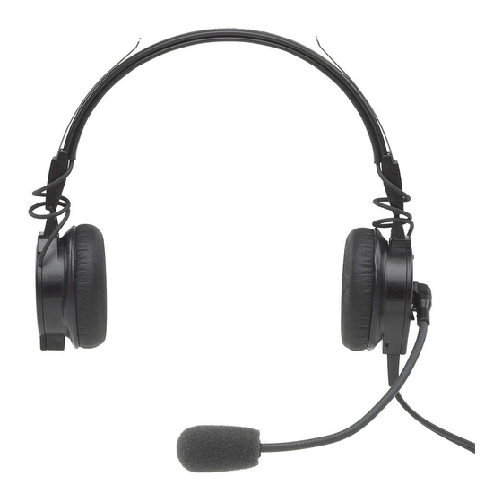
Lightweight design with soft, pliable cushions, adjustable headband, extended frequency drivers, and a noise canceling electret microphone result in a comfortable headset providing the ultimate in clear, understandable communications. The Airman 850 headset with boom microphone is approved for aircraft use under FAA TSO’s C57a and C58a. Models covered This manual only covers models listed here. - Page 7 Airman 850 Description | en Model Description Connector and wiring used number 301317-300 Airman 850 Headset, Single- PJ-068 (or equivalent) & PJ-055 (or sided equivalent) Connector wiring diagram for catalog numbers 301317-000; -003; -101; -200; -201; -300; and -400, page 18...
-
Page 8: Disassembly / Assembly
Airman 850 Disassembly / Assembly Disassembly The following procedure allows for complete disassembly of the Airman 850 final assembly. Notice! The removal process requires the steps to be followed in order. For example, to remove the boom assembly, item 13, all steps before the Removing the Boom Assembly step must be completed and in the listed order. -
Page 9: Remove Boom Assembly / Cover (Item 13)
Airman 850 Disassembly / Assembly | en Once freed, carefully remove the sleeve from the housing. 3.1.4 Remove boom assembly / cover (item 13) To remove the boom assembly/cover, do the following: Insert a tweezers or small flat head screwdriver between the circuit board (item 9) and the housing (item 6), gently pushing the cover away from the housing. -
Page 10: Assembly
Please take care to properly align parts and wires to ensure proper operation. See disassembly procedure, parts lists, assembly diagrams, and wiring diagrams for reference. 22 23 Figure 3.1: Airman 850 headset, dual sided, exploded view 09-2021 | V07 | F.01U.264.819 Bosch Security Systems LLC Customer maintenance manual... - Page 11 Airman 850 Disassembly / Assembly | en Figure 3.2: Airman 850 headset, single sided, exploded view Bosch Security Systems LLC 09-2021 | V07 | F.01U.264.819 Customer maintenance manual...
- Page 12 | Disassembly / Assembly Airman 850 Catch 10° (Push from other side of faceplate Catch (Push from other Assemble side of faceplate Remove Figure 3.3: Faceplate disassembly/assembly view 09-2021 | V07 | F.01U.264.819 Bosch Security Systems LLC Customer maintenance manual...
-
Page 13: Parts List
Parts list General When replacing parts, consult the illustrations in Assembly, page 10 and the parts lists. Choose the parts corresponding to the catalog/model. Airman 850, catalog number 301317-000; -002; -101; -200; -201; -300; and -400 Model Item CTN SAP number... - Page 14 800789000 F01U153679 Boom assembly 800789100 F01U153680 Boom assembly AIRMAN7-0900 F01U110451 Windscreen 2 pcs for Airman 850, 7, 8, 8+ AIRMAN7-9050 F01U393945 50 pc windscreen bulk Airman 850, 7, 8, 8+ AIRMAN7-9100 F01U393946 100 pc windscreen bulk Airman 850, 7, 8, 8+...
- Page 15 Airman 850 Parts list | en S-F01U345383 F01U345383 ANR microphone 35398005 F01U146873 5-pin XLR connector Either part number is acceptable. This item has 10 pieces. Only one or two springs are needed per unit. Not shown. This item is part of the headband assembly (no.1) or can be purchased separately.
-
Page 16: Wiring Diagrams
Airman 850 wiring diagram (catalog numbers 301317-000; -002; -003; -101; and -400) Figure 5.1: Top side, Airman 850, dual sided wiring diagram Figure 5.2: Bottom side, Airman 850 headset, dual sided wiring diagram 09-2021 | V07 | F.01U.264.819 Bosch Security Systems LLC... -
Page 17: Airman 850 Wiring Diagram (Catalog Numbers 301317-200; -201; And -300)
Airman 850 Wiring diagrams | en Airman 850 wiring diagram (catalog numbers 301317-200; -201; and -300) Figure 5.3: Airman 850 headset, single sided wiring diagram Bosch Security Systems LLC 09-2021 | V07 | F.01U.264.819 Customer maintenance manual... -
Page 18: Connector Views / Wiring Diagrams
Connector views / wiring diagrams 5.3.1 Connector view for catalog numbers 301317-000; -003; -200; -300; and -400 Figure 5.4: Airman 850 headset, connector view (molded plugs) 5.3.2 Connector view for catalog numbers 301317-101; and -201 Figure 5.5: Airman 850 headset, connector view (mechanical plugs) 5.3.3... -
Page 19: Connector Wiring Diagram For Catalog Number 301317-002 (5-Pin Xlr)
Connector wiring diagram for catalog number 301317-002 (5-pin XLR) Pin 5 N/C Pin 1 White Pin 4 Black (shield) Pin 2 Yellow Pin 3 Red Figure 5.8: Airman 850 headset, 5-pin XLR wiring diagram Bosch Security Systems LLC 09-2021 | V07 | F.01U.264.819 Customer maintenance manual... -
Page 20: Maintenance
MIC - 1/4W 5 % Figure 6.1: Airman 850 headset boom microphone sensitivity check and adjustment test circuit Calibrate a lab microphone, either self-contained (such as Larson Davis sound level meter) or a separate measuring microphone with supporting equipment (such as Bruel and Kjaer type 4192 with type 2669-B preamp). -
Page 21: Microphone Sensitivity Adjustment
For more information, see the illustration below. Clockwise adjustment increases output level. Gain Adjustment Figure 6.2: Airman 850 headset, boom microphone gain adjustment location 6.1.3 Troubleshooting mic failure The microphone circuitry is in two (2) parts; the boom microphone preamp and main amp located on the main circuit board. - Page 22 | Maintenance Airman 850 GREEN COPPER Figure 6.3: Airman 850 headset, boom assembly reference view Red Wire Vcc = 3.3V Green Wire DEVICE UNDER TEST V out Copper Wire Ground Follow the steps 4 through 8 in Microphone / amplifier sensitivity check, page 20 , and then measure the output of the boom microphone.
-
Page 23: Operational Test Of The Microphone And Headphone
Airman 850 Maintenance | en Operational test of the microphone and headphone Notice! This method is an alternative to Speaker validation and adjustment, page 23 and requires a known-good headset and an intercom. Insert the microphone and headphone plugs of a known-good (a.k.a. Reference) headset into the intercom jacks on the “Copilot”... -
Page 24: Anr Validation And Adjustment
| Maintenance Airman 850 Frequency response: Must meet standards outlined in Receiver frequency response table in Specifications, page 29 . To measure the speaker, do the following: Using a B&K type 4153 with 6cc coupler or equivalent, place the headset speaker on an artificial ear, fitted with the appropriate coupler. -
Page 25: Minimum Attenuation Requirements (Linearize Between Points)
Upper limit 1000 6.4.3 ANR test procedure Required equipment The Airman 850 ANR test and adjustment procedure requires the following acoustic test equipment and custom fixture: – Audio Test System (Audio Precision or equivalent test system) or – Artificial Mouth (Bruel & Kjaer 4227) or equivalent speaker –... - Page 26 | Maintenance Airman 850 Custom ANR fixture Figure 6.6: Custom ANR test fixture with headset Testing ANR To test ANR, do the following: Create a standard microphone test setup. A 1VRMS stimulus, such as swept sine or pseudo pink noise BP (Bandpassed) with 400Hz center frequency, should be applied to artificial mouth (or equivalent speaker) mounted to test fixture.
-
Page 27: Cleaning The Unit
Airman 850 Maintenance | en Cleaning the unit Warning! Use a mild detergent or isopropyl alcohol wipes to clean the plastic and metal headset parts and ear cushions (not foam windscreen). Do not soak or allow the cleaner to puddle on the unit and sit for long periods of time. The cleaner should wipe off or evaporate quickly. -
Page 28: Troubleshooting
| Troubleshooting Airman 850 Troubleshooting Troubleshooting chart Check Check Check Check Check Check Check plugs main amplifier overhead speakers boom circuit cord gain cord boards adjust assembly Receiver inoperative Microphone inoperative Receiver intermittent Microphone intermittent Distorted receiver signal Distorted... -
Page 29: Specifications
Airman 850 Specifications | en Specifications Receivers Type: Dynamic Impedance: see table below Caution! Damage could occur to avionics equipment if used with headset versions, which are not manufactured for use with 600 Ohm headsets. If in doubt, consult the avionics equipment manufacturer. - Page 30 150 Ohms 301317-002 Airman 850 Headset, Dual-sided 600 Ohms 301317-003 Airman 850 Headset, Dual-sided 600 Ohms 301317-101 Airman 850 Headset, Dual-sided, customer specific 150 Ohms 301317-200 Airman 850 Headset, Single-sided 150 Ohms 301317-201 Airman 850 Headset, Single-sided, customer 150 Ohms specific...
- Page 31 Airman 850 Appendices | en Appendices Figure 9.1: ANR test fixture drawing Bosch Security Systems LLC 09-2021 | V07 | F.01U.264.819 Customer maintenance manual...
- Page 32 | Appendices Airman 850 09-2021 | V07 | F.01U.264.819 Bosch Security Systems LLC Customer maintenance manual...
- Page 34 TELEX 12000 Portland Avenue South Burnsville MN 55337 www.telex.com © Bosch Security Systems, LLC, 2021 202109282043...
Need help?
Do you have a question about the Airman 850 and is the answer not in the manual?
Questions and answers